Mounting
6.3 Mounting the control unit on the rear wall of the control cabinet
NCU 7x0.2
Manual, 02/2011, 6FC5397-0AP20-0BA0
43
Procedure
1. Remove the spacers.
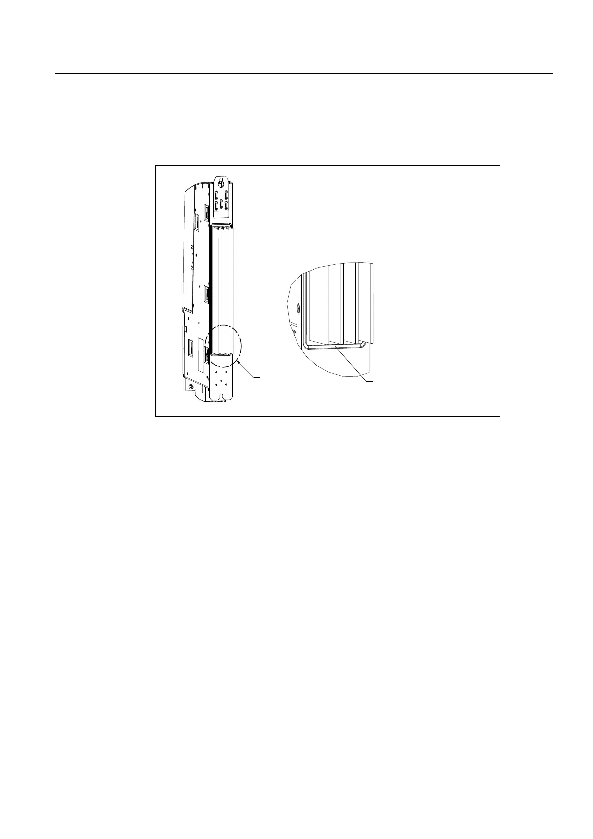
2. Fit the seal around the cooling fins of the control unit.
3ODFHWKHVHDOIRUVHJUHJDWHGKHDW
UHPRYDO)&$$$$
LQWKHKHDWVLQNVORW
$
$
3. Loosen the three M3 screws on the upper clip and push the clip up until the upper hole
protrudes beyond the housing.
4. Tighten up the three screws on the clip again.
5. Mount the top and bottom of the control unit with heat sink directly on the rear wall of the
control cabinet using two M6 screws (6 Nm) (
① see figure titled "Panel cutout").
See also
Variants (Page 16)
 Loading...


