Mounting
6.4 Lateral mounting of Control Unit on the SINAMICS drive line-up
NCU 7x0.2
44 Manual, 02/2011, 6FC5397-0AP20-0BA0
6.4 Lateral mounting of Control Unit on the SINAMICS drive line-up
Introduction
The Control Unit can also be mounted laterally on the SINAMICS drive line-up, on the side
panel of a SINAMIC S120 Line Module. The required mounting elements are supplied with
the Line Module.
Note
Exception: NCU 710.2 and NCU 720.2 cannot be laterally mounted on the SINAMICS drive
line-up.
Proceed as follows
The Line Module has five mounting elements on the left-hand side. To mount the Control
Unit, proceed as follows:
1. Remove the spacers from the Control Unit.
2. Position the Control Unit on the left-hand side of the Line Module. The mounting fixtures
fit exactly in the five cutouts on the Control Unit.
3. Push the two units together.
4. Press down on the Control Unit until it engages and is securely connected to the Line
Module.
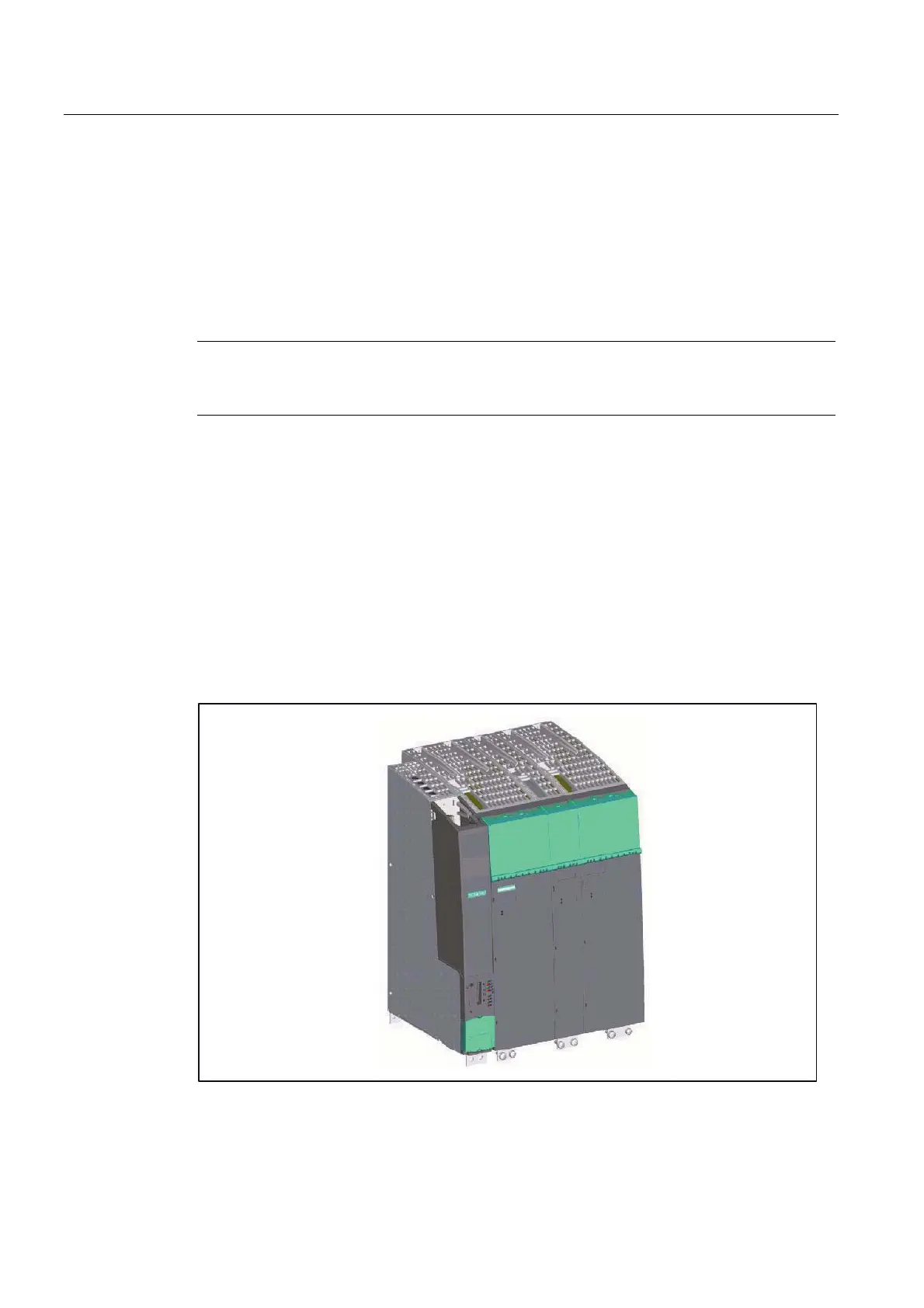
Figure 6-4 SINAMICS group with Control Unit
 Loading...


