Siemens Industry, Inc.
Building Technologies Division
P/N 315-033240-1310
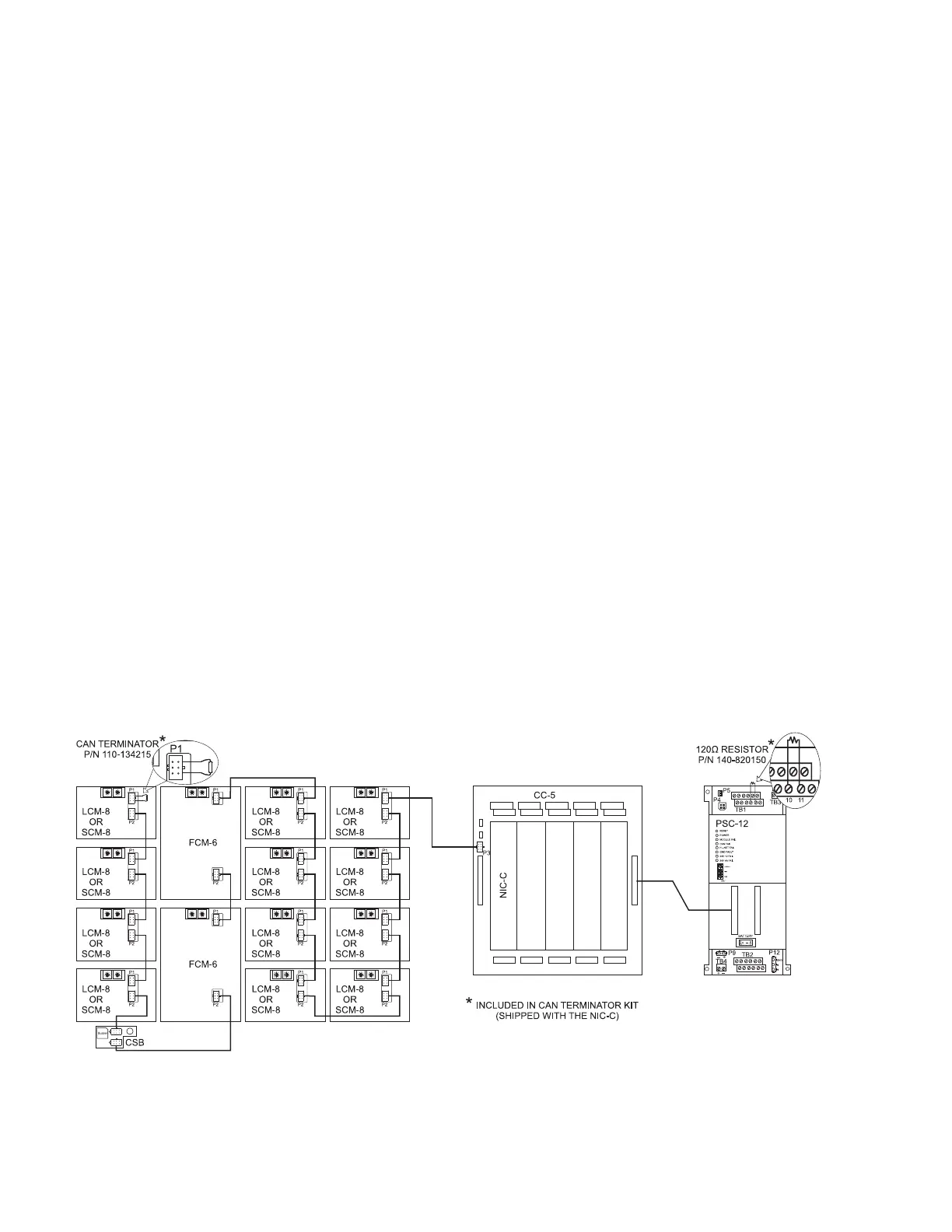
To Connect the Internal CAN Bus
1. Install the CCL cable into P3 of the CC-5 in the upper left corner of the
enclosure.
2. Install the other end of the CCL cable into the first CAN module on the
inner door.
3. Observe the location of the CAN termination devices. Install one CAN
terminator P/N 110-134215 in the last CAN module on the inner door. Install
the 120 Ohm CAN termination resistor P/N 140-820150 into TB1 10 and 11
on the PSC-12.
4. The NIC-C may be installed into any open slot of a CC-5.
To Connect the External CAN Bus
1. Loosen the screw of the terminal by turning it counterclockwise.
2. Insert the wire into the side of the terminal block
3. Tighten the screw of the terminal block by turning it clockwise.
4. Observe the location of the CAN termination devices. Install one CAN
terminator P/N 110-134215 in the last CAN module on the inner door. If no
CAN modules are installed on the inner door inset the CAN terminator into
P3 of the CC-5 where the NIC-C is installed.
5. Install the second CAN terminator in the last CAN module in the remote
enclosure.
6. The NIC-C may be installed into any open slot of a CC-5.
Figure 10
CAN Wiring - Single Enclosure

 Loading...