Siemens Industry, Inc.
Building Technologies Division
P/N 315-033240-139
NOTES:
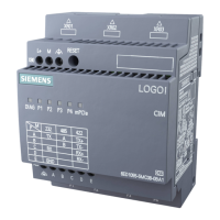
1. No EOLR required for NIC-C.
2. The screw terminals can accommodate one
12-24AWG or two 16-24AWG.
3. From the NCC-2F to NIM-1R, NIM-1W or
NCC-2F:
80 Ohms max. per pair.
Unshielded twisted pair - .5μF line to line
Shielded twisted pair - .3μF line to line, .4μF
line to shield
4. From the NCC-2F to NIC-C:
2000 feet (33.8 ohms) max. per pair between
CC-5s/CC-2s.
Figure 8
Connecting To An XNET
12345678
910111213141516
17 18 19 20 21 22 23 24
SEE NOTE 7
DO NOT USE
D
N
T
E
DO NOT USE DO NOT USE
ONE SLOT OF CC-5
NIC-C
12345
PAIR A
SUPERVISED
POWER LIMITED
PAIR B
(OMIT FOR STYLE 4)
SUPERVISED
POWER LIMITED
LOCATED INSIDE NCC/
DESIGO CC/VNT
NOTE:
IF THE NCC/DESIGO CC/VNT
IS LOCATED AT THE END OF THE
XNET NETWORK, INSTALL EOLR
P/N 140-820350 ACROSS
TERMINALS 1 & 2 AND 3 & 4.
NCC-2F
MOM-4
TB3 OR TB4
NIM-1R / NIM-1W
1
2
3
4
TO ADDITIONAL
NIM-1Rs, NIM-1Ws,
NCC-2Fs OR NIC-C
(MUST BE IN SAME ENCLOSURE AS THE PMI/
PMI-2/PMI-3 [XLS], FCM2041-U2 [DESIGO FIRE
SAFETY MODULAR], FCM2041-U3 [CERBERUS
PRO MODULAR])
TB2
NIM-1M
NIM-1W
MOM-2
1 2 3 4
TB4
TB6
A PAIR
*
*
MOM2-XMP
+
-
B PAI
B PAIR
(OMIT FOR
CLASS-B/
STYLE 4
(ULC DCLB))
TO
PSC-12
TB3
TO
COMPANION
NIM-1M
24V
24V RET
DO NOT USE
DO NOT USE
1 2 3 4 5 6 7 8
9 10 11 12 13 14 15 16
NIC-C
A PAIR
EOLR P/N 140-099066
(SUPPLIED WITH NIM-1W)
*
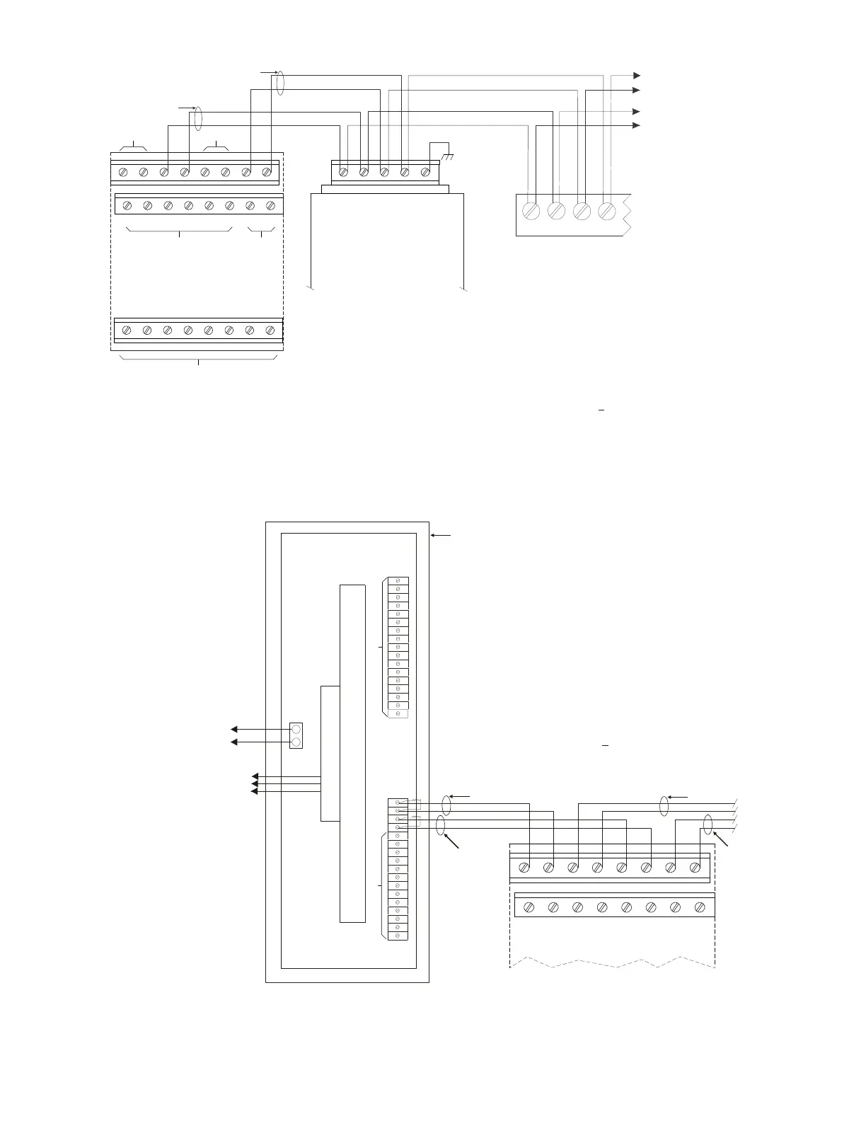
Figure 9
Wiring The NIC-C To An XNET Bridge
NOTES:
1. Refer to NIM-1W Installation Instructions,
P/N 315-099106 for NIM-1W setup and
NIM-1M setup and wiring instructions.
2. No EOLR required at the NIC-C.
3. All wiring power limited to NFPA 70 per
NEC 760.
4. Class-B/Style 4 Bridge shown. For Class-X/
Style 7, a second NIM-1W/NIM-1M is
required.
5. The NIC-C and the NIM-1W /NIM-1M must
be in the same enclosure.
6. Positive or negative ground fault detected
at <10K ohms on pins 1 - 8.
Unshielded twisted pair
.25μF max. line to line
Shielded twisted pair
.15μF max. line to line
.2μF max. line to shield
5. Use twisted pair or twisted shielded pair.
6. Terminate shields at one end only.
7. Power limited to NFPA 70 per NEC 760.
8. CC-5 terminals 9 - 14 are not connected and
can be used to tie shields together.
9. Positive or negative ground fault detected at
<10K ohms on pins 3-4, 7-8 of the NIC-C.
10. Each pair independently supervised.
11. Maximum voltage 8V P-P.
12. Maximum current 75mA during message
transmission.

 Loading...