NK822x Structure and Functions
17
Building Technologies 048_DMS_NK8000_ICC_MP4.40_A6V10062437_a_en.doc
Fire Safety & Security Products 06.2011
4 NK822x Structure and Functions
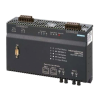
The NK822x is composed of an electronic board (with optional plug-ins) installed in
a compact and robust plastic box.
Fig. 1 NK822x Ethernet port (NK8223 in this example)
4.1 Front panel
The front panel of the NK822x houses 9 LED's. The five LED's on the left side are,
from top to bottom:
Front panel LED Functions
Power (LED green) Power (hardware – controlled)
Vital functions (LED green) Software vitality (blinking)
Tamper (LED bicolour) Unit tamper:
– Red means tamper alarm (hardware controlled)
– Green means tamper disabled (from management station)
Download (LED red) NK822x network diagnostics:
– Off = Status OK
– Blinking (1 flash) = Missing identification from NS8xxx
– Blinking (2 flashes) = Not used
– Blinking (3 flashes) = Default mode ( switch settings in
section 4.2): FTP channel open
– On = Critical/hardware fault
Diagnostics (LED yellow) NK822x internal interface diagnostics:
– Off = Status OK
– Blinking (1 flash) = Missing or insufficient license
– Blinking (2 flashes) = Trouble with the I
2
C bus to I/O modules
– Blinking (3 flashes) = Trouble with the LON interface
– Blinking (4 flashes) = Trouble with the serial/network interface
– Blinking (5 flashes) = Trouble with DLL or RCLOCK file(s)
– On = Critical/hardware fault
Tab.1. LED functions on the front panel, left side
The four LED's on the right side are, from top to bottom:
Front panel LED (right Functions
Com1 Status Com1
Com2 Status Com2
Com3 Status Com3
Com4 Status Com4
Red: RX
Green: TX
Tab.2. LED functions on the front panel, right side
 Loading...