Hardware installation
5
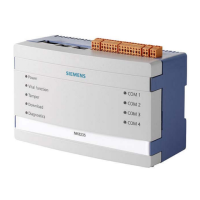
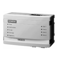
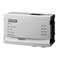
NK822x hardware installation
42
Building Technologies A6V10062437_a_en
Fire Safety & Security Products 30.06.2013
See LON interface [➙ 21] for additional information.
LON TP/FT-10 network segment characteristics.
Characteristic Bus topology Free topology
Max. cable length (UTP Cat.4) [m] 1,400 500
Termination 2 x 100Ω, 1/8W
at each end of
segment
1 x 50Ω, 1/8W
at centre of segment
Max. number of nodes per segment 64
Max. number of repeaters 4
Polarity insensitive Yes
NK822x has a built-in termination resistor (100Ω) for a doubly terminated bus topology
that can be enabled by closing the internal jumper JP6.
See Internal jumpers [➙ 19] and LON interface [➙ 21].
Note: Please refer to the Echelon Manual for detailed specification on how to set up a
LON network: http://www.echelon.com/Support/docum
entation/, section: Engineering
Bulletins > Media & Wiring.
DIN Rail Installation
The modules are supplied in a plastic box that can be easily attached to the DIN rail by
hooking it on the top of the rail and pressing it in on the opposite side. To detach the
box, pull downward on the tab located at the rear of the module. The I/O modules are
mounted the same way.
Note: Before removing the box, carefully disconnect the flat cable (bus) of the I
2
C
module, as well as the power supply cables.

 Loading...

