Do you have a question about the Siemens OLM/G11-1300 V4.0 and is the answer not in the manual?
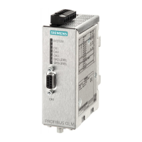
| Product type designation | OLM/G11-1300 V4.0 |
|---|---|
| Product version | V4.0 |
| Protection class | IP20 |
| Category | Control Unit |
| Manufacturer | Siemens |
| Operating voltage | 24 V DC |
| Ambient temperature | 0°C to 60°C |
| Device Type | Optical Link Module |
| Network Type | PROFIBUS |
| Fiber Type | Multimode |
| Number of Ports | 2 |
| Isolation Voltage | 500 V |
| Operating Temperature | 0°C to 60°C |
| Mounting | DIN rail |
| Function | Optical networking of PROFIBUS and other automation systems |
Defines safety levels (Danger, Warning, Caution, Notice) and their associated symbols and meanings.
Lists the network topologies that can be implemented with PROFIBUS OLMs: point-to-point, bus, star, and redundant ring.
Details the implementation of a linear or bus topology using PROFIBUS OLMs connected by two-fiber cables.
Provides critical safety warnings and notices related to the installation and operation of PROFIBUS OLMs.
Explains DIL switch settings for compatibility, electrical/optical channel modes, and transmit power reduction.
Covers transmit power reduction, specific switch functions, mixed OLM operation, and connecting optical cables.
Covers general installation, electromagnetic compatibility, and measures for suppressing self-inductances.
Provides guidance on device/cable arrangement, shielding, grounding, and potential differences for optimal installation.
Provides detailed instructions for connecting optical cables, including connector checks and cable management.
Explains the connection of electrical RS-485 bus cables to the OLM module's D-sub port.
Provides essential notes on RS-485 cable connection, compatibility, safety, and temperature considerations.
Specifies the requirement for a stabilized safety extra-low voltage (24 V DC) for supplying the OLM module and redundant supply.
Maps LED/signaling contact status to causes and provides troubleshooting steps for identified errors.
Details configuration requirements and slot time calculation for redundant optical rings.