Installation and Maintenance
5.6 Receive Level of the Optical Channels
SIMATIC NET PROFIBUS, Optical Link Module
36 Operating Instructions, 07/2008, A2B00065774O, Edition V1.5
Measured voltage / V
≈ ≈
≈
5.6 Receive Level of the Optical Channels
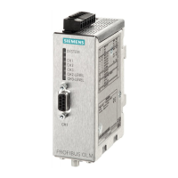
Figure 5-11 Position of the level
recording connections
The receive level of the two optical channels CH2 und CH3 can
be measured using a standard voltmeter via the measurement
sockets. The voltmeter can be connected and disconnected
while the device is operating. The OLM is protected against a
short circuit at the measurement sockets; data transmission is
not influenced. The receive level of the two optical channels can
be read in on a PLC using floating high impedance analog
inputs.
This allows
– the incoming optical power to be documented, e.g. for later
measurement (aging, damage)
– a good/bad test to be carried out (limit value).
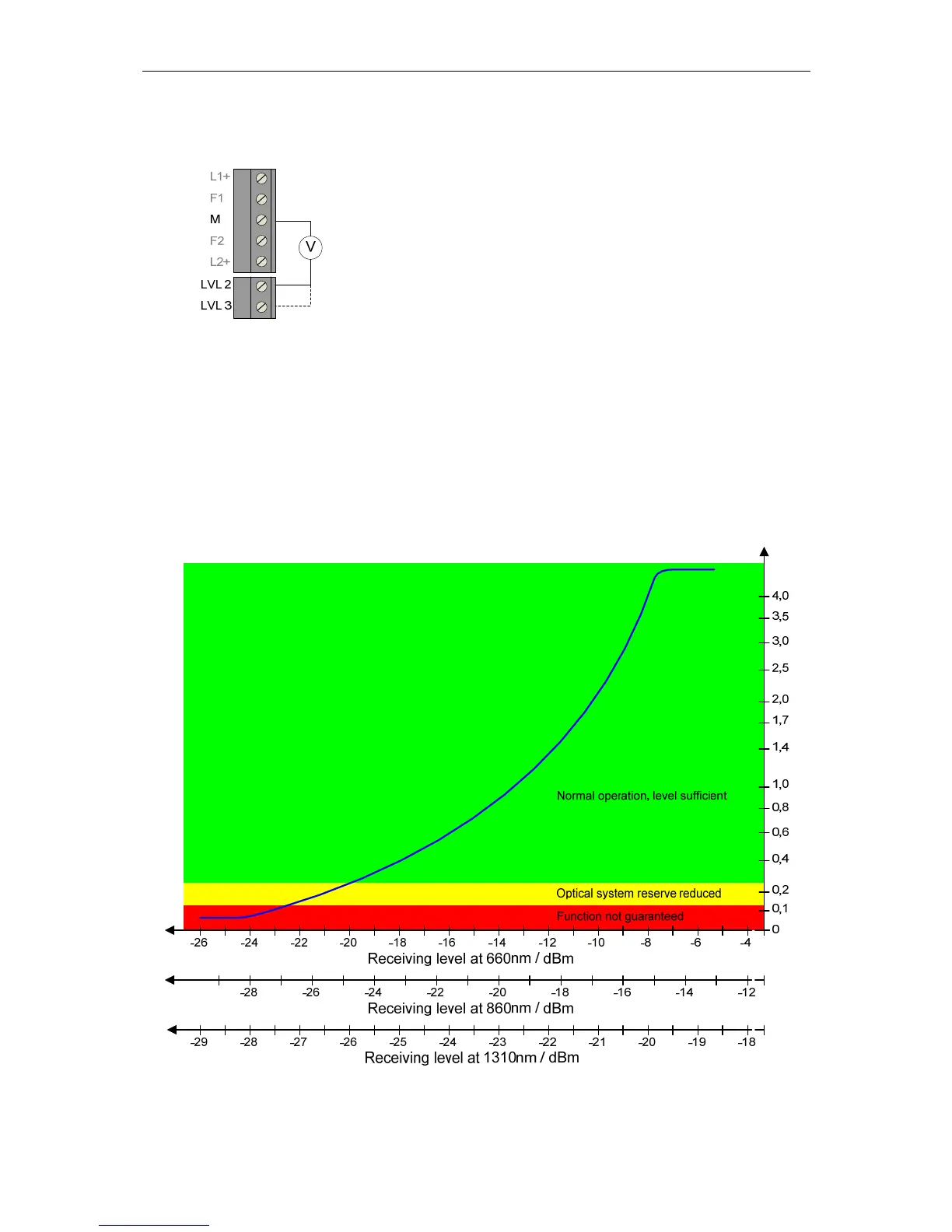
The measurement must be performed with a high-resistance, ungrounded voltmeter. The ground
connector must not be connected to the housing; otherwise the data traffic could be disturbed. To
meet the EMC requirements, the length of the connected measuring cables must not exceed 3 m. The
quality of the bus traffic can be estimated based on the receiving levels in the following diagram:
Figure 5-12 Relationship between measured output voltage and signal quality
 Loading...