EasyManua.ls Logo

Siemens OLM/G12-1300 V4.0 User Manual

Siemens OLM/G12-1300 V4.0
61 pages
To Next Page IconTo Next Page
Page #1 background imageLoading...
Page #1 background image
Preface
1
Introduction
2
Network Topologies
3
Product Characteristics
4
Installation and Maintenance
5
Approvals and Marks
6
References
7
Drawings
8
SIMATIC NET PROFIBUS
Optical Link Module
OLM / P11 V4.0
OLM / P12 V4.0
OLM / P11 V4.0
OLM / G12 V4.0
OLM / G12-EEC V4.0
OLM / G11-1300 V4.0
OLM / G12-1300 V4.0
Operating Instructions
07/2008
A2B00065774O, Edition V1.5

Table of Contents

Question and Answer IconNeed help?

Do you have a question about the Siemens OLM/G12-1300 V4.0 and is the answer not in the manual?

Siemens OLM/G12-1300 V4.0 Specifications

General IconGeneral
BrandSiemens
ModelOLM/G12-1300 V4.0
CategoryControl Unit
LanguageEnglish

Summary

Preface and Purpose

Introduction to PROFIBUS OLM

PROFIBUS OLM Overview

Overview of PROFIBUS OLM4.0 product family functions and capabilities.

Network Topologies

Bus Topology with Monitoring and Segmentation

Using mode for disrupted segments and monitoring mechanisms.

Redundant Ring with Two OLMs Configuration

Details configurations and LED behavior for two-OLM redundant rings.

Product Characteristics

Technical Specifications Overview

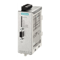
Lists specifications like power supply, current, signal transmission, and status signaling.

Product Specifications and Approvals

Details approvals, electrical/optical channel specs, wavelength, and EMC.

Safety Related Installation Notices

Safety notices for using PROFIBUS OLMs, including voltage and hazard warnings.

Setting Compatibility Mode

Explains how to enable/disable compatibility with previous generation OLMs.

DIL Switch Settings for Compatibility and Mode

Details DIL switch significance for compatibility and mode settings.

Installation and Maintenance

Connecting Optical Cables

Instructions for connecting fiber-optic cables, including BFOC connectors and bending radii.

RS-485 Bus Cable Connection

Explains connecting RS-485 bus cables using the D-sub connector.

Connecting the Operating Power Supply

Instructions for connecting the 24 V DC operating power supply.

Optical Channel Receive Level Measurement

How to measure optical channel receive levels using a voltmeter.

LED Displays and Possible Causes

Lists possible causes for LED status and corresponding signaling contact output.

Troubleshooting Electrical Channel (CH1) Errors

Troubleshooting steps for errors on the electrical channel (CH1).

Troubleshooting Optical Channel (CH2/CH3) Errors

Troubleshooting steps for errors on optical channels (CH2/CH3).

Related product manuals