Installation and Maintenance
5.2 Installation of the Modules
SIMATIC NET PROFIBUS, Optical Link Module
Operating Instructions, 07/2008, A2B00065774O, Edition V1.5
31
5.2 Installation of the Modules
Installation options
The OLM modules can either be mounted on a 35 mm rail according to DIN EN
50022 or on a flat surface with the help of a mounting plate.
¾ Choose the location so that the climatic and mechanical limit values listed in the
technical specifications can be met.
¾ Make sure there is enough space to connect the bus and voltage supply lines.
¾ Connect the fiber-optic cables before you install the modules. This makes it easier
to connect the fiber-optic cables.
¾ Only install the modules on a rail or a mounting plate that is grounded with low
resistance and inductance. No other grounding measures are necessary.
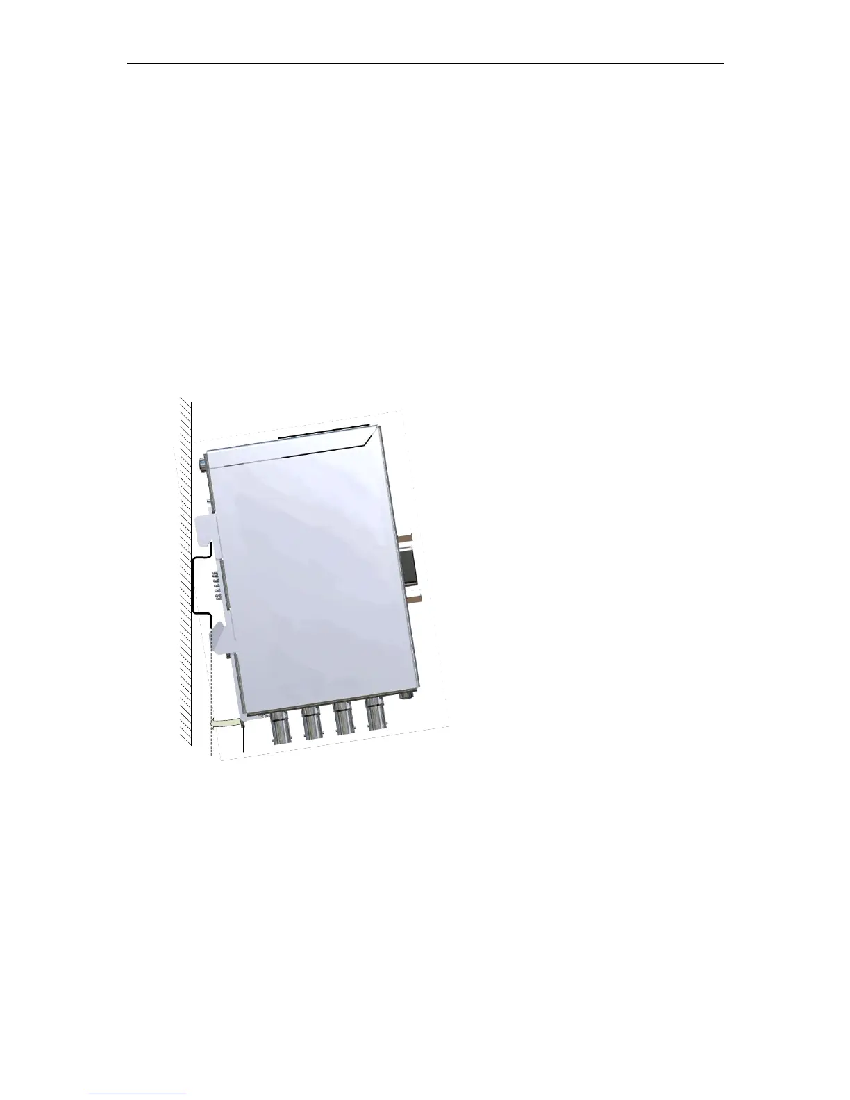
Figure 5-4 Installation of a module on a standard DIN rail
Installation on a DIN rail
¾ Fit the upper securing hooks onto the rail
and push in the lower part towards the rail,
as shown in Figure 5-4 , until it locks
audibly in place. To uninstall the module,
pull the locking slide downwards.
Locking slide
 Loading...