CM2N4625E / 02.1999 Siemens Building Technologies
4/10 Landis & Staefa Division
Refer to "Technical design" and "Commissioning notes" in this data sheet.
4626Z21
A
B
10
9
3
2
1
13
8
7
6
PUSH
4
5
90°
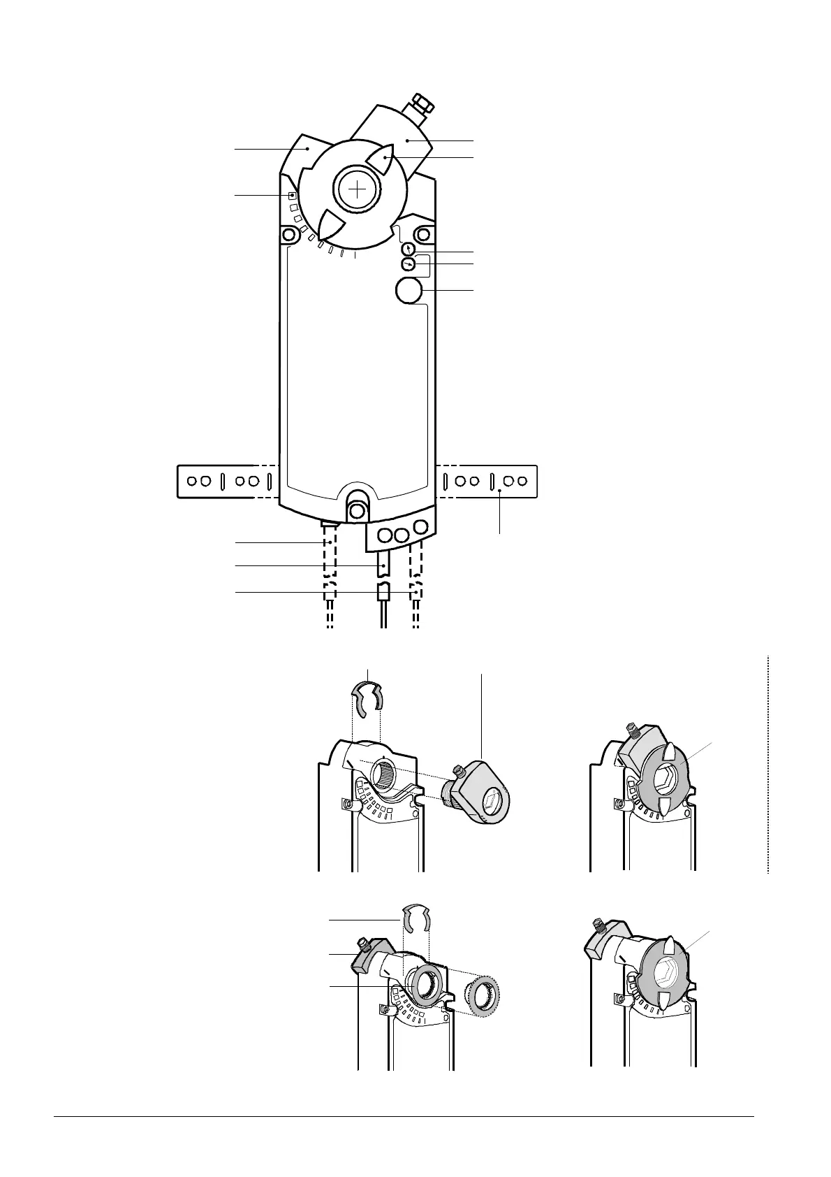
1 Housing
2 Angle of rotation scale 0°...90°
3 Connection cable for positioner
4 Connection cable for power supply
5 Connection cable for auxiliary
switches
6 Gear train disengagement button
7, 8 Adjustment dials for auxiliary
switches A and B
9 Position indicator
10 Self-centering shaft adapter
11 Locking ring for shaft adapter
12 Adapter for position indicator
13 Mounting bracket
4626Z23
10
11
4626Z25
9
4626Z22
11
12
10
4626Z24
9
Setting and operating
elements
Arrangement for long
shaft adapters
Arrangement for short
shaft adapters

 Loading...