Siemens Building Technologies CM2N4625E / 02.1999
Landis & Staefa Division 9/10
All wires are color-coded and labeled.
Connection
cable
Wire
labeling
Designation Color L&G terminal
code
Actuators 1 System potential AC 24 V red G
AC 24 V 6 Control signal AC 24 V (0 V), clockwise purple Y1
7 Control signal AC 24 V (0 V), counter clockwise orange Y2
Actuators 4 Neutral conductor blue N
AC 230 V 6 Control signal AC 230 V, clockwise black Y1
7 Control signal AC 230 V,counter clockwise white Y2
Auxiliary S1
Switch A Input gray/red
Q11
switches S2 Switch A Normally closed contact gray/blue Q12
S3 Switch A Normally open contact gray/pink Q14
S4 Switch B Input black/red Q21
S5 Switch B Normally closed contact black/blue Q22
S6 Switch B Normally open contact black/pink Q24
Positioner P1 Potentiometer 0...100 % (P1-P2) white/red a
P2 Potentiometer pick-off white/blue b
P3 Potentiometer 100... 0 % (P3-P2) white/pink c
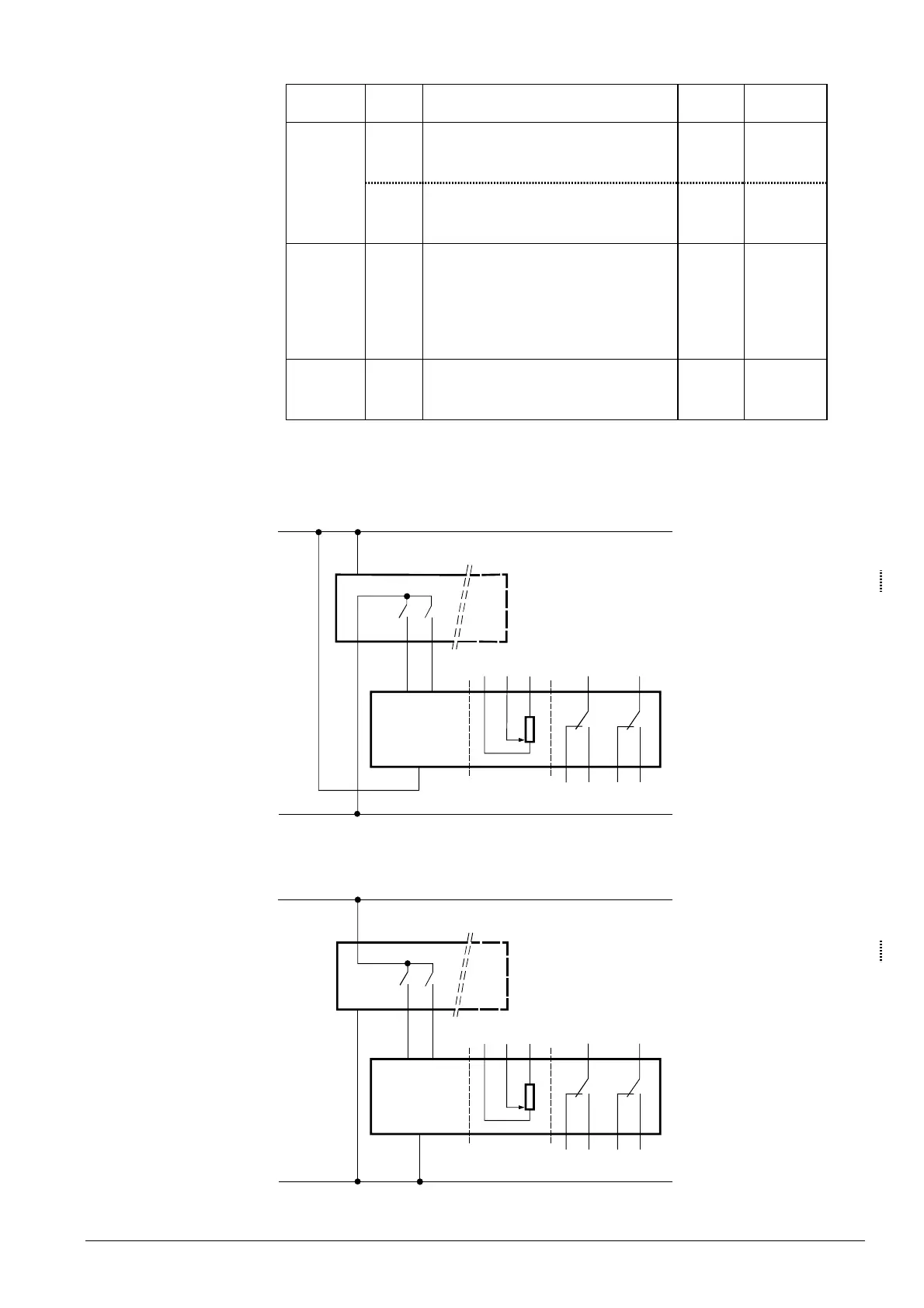
4626A01
(Y1)
(G)
(G0)
SP
SN
AC 24 V
GBB13...
1
S2 S3 S5 S6
7
P3 S1 S4
Y
6P1
P2
(Y2)
N
AC 24 V (SELV/PELV)
N
Regulator or controller
Y
Actuator GIB13...,
three-position, AC 24 V
SP System potential AC 24 V
SN System neutral
4626A02
(L)
(N)
L
N
AC 230 V
GBB33...
4S2S3S5S6
7P3S1S4
Y
6P1P2
N
(Y1) (Y2)
AC 230 V
N
Regulator or controller
Y
Actuator GIB33...,
three-position, AC 230 V
L Phase conductor AC 230 V
N Neutral conductor
Cable labelin
Connection diagrams
GIB131.1E
GIB135.1E
GIB136.1E
GIB331.1E
GIB335.1E
GIB336.1E

 Loading...