25/44
Siem ens GMA..1 actuators with spring return CM2Z4614en
Building Technologies 2018-01-11
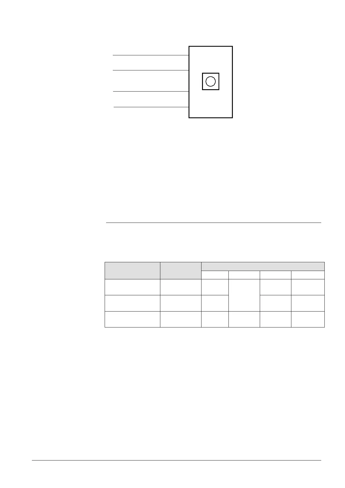
The diagram shows the currents in the connecting lines for one actuator.
M
0 V
G0
AC 24 V
DC 0...10 V
G
Y
U
GMA16..1
1
2
9
8
(DC 0...10 V)
AC 0.21 A
AC 0.21 A
4614G07
Determining the line lengths for four actuators GMA16..1 at AC 24 V supply. Only the
AC currents in line 1 (G) and 2 (G0) determine the line sizing.
Max. permissible voltage drop = 4% per line.
∂ Consumption: 4 x 5 VA = 20 VA
∂ Line current: 4 x 0.21 A = 0.84 A
∂ Permissible single line length for G, G0:
98 m at 1.5 mm
2
line cross section, or
163 m at 2.5 mm
2
line cross section.
6.4.2 DC 24 V supply
With DC supply, the G0 line has a DC 0.15 A supply current and a DC 0.1 mA
positioning signal current (from Y = DC 0...10 V). The entire DC voltage drop on the G0
line directly impacts positioning signal Y.
Max. permissible voltage drop on G0 line = 1 %.
Power
consumption
Perm. voltage drop for line
1 (G) 2 (G0) 8 (Y) 9 (U)
Operating voltage:
DC 24 V
3.5 W
4 % of
DC 24 V
1 % of
DC 24 V
Positioning signal:
Y = DC 0...10 V
0.001 W
1 % of
DC 10 V
Position indicator:
U = DC 0...10 V
0.01 W
1 % of
DC 10 V
P&I diagram:
Conduction currents at
AC 24 V
Example:
Parallel connection of four
actuators
Power consumption and
perm. voltage drop with
one actuator

 Loading...