Document No. 125-1902
User Guide
June 26, 2018
Siemens Industry, Inc. Page 7 of 16
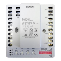
Exhaust Fan Operation and Setting
Figure 8. Relay Connection.
The exhaust fan contacts are 24V dry contacts only,
and are labeled Q31 and Q32. An external line
voltage contactor is required to operate the exhaust
fan.
If the EX FAN potentiometer is turned fully counter-
clockwise to 0%, the EX FAN feature is disabled.
This feature allows the exhaust fan operation to be
disabled instead of being operated at constant ON.
The exhaust fan shut-off point is selected by setting
the EX FAN potentiometer to the desired level. See
Figure 7.
When the damper position reaches the exhaust fan
setpoint, the exhaust fan relay will be energized. A
Green exhaust fan LED indicates that the exhaust
fan is ON.
Cooling Stage Operation
Figure 9. Cooling Stage Operation.
The Economizer Controller accepts inputs for single-
and two-stage cooling inputs, and reroutes to the
RTU through the relay connection CC1 and CC2.
The operation of the cooling stages is determined by
the availability of Free Cooling provided by the
economizer operation mode. SeeTable 4.
Based on the use of Free Cooling, the operating
modes are as follows:
• Y1 is Stage 1 Cooling Demand.
• Y2 is Stage 2 Cooling Demand.
• Free Cooling is always the first cooling stage.
• The Cool Stage 1 call from the Commercial
Thermostat (Y1) energizes the CC1 input to the
Economizer Controller.
• The Cool Stage 2 call from the Commercial
Thermostat (Y2) energizes the CC2 input to the
Economizer Controller.
Table 4. Cooling Stage I/O Logic.
* If OAT<56°F, then Relay 2 is always OFF to
disable Cooling Stage 2. Otherwise, if both stages of
cooling (Y1 and Y2) are ON for more than 5
minutes, Y2 remains ON, and the OAT is greater
than 56°F, then Relay 2 will energize to allow Y2
pass-through to enable Cooling Stage 2.
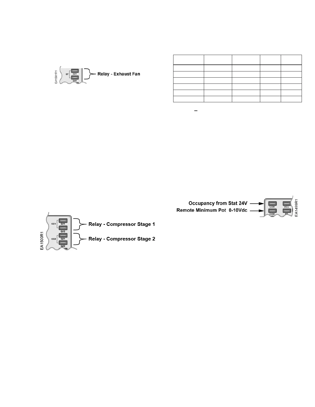
Remote Positioning Potentiometer
BSG61, 0 to 10 Vdc for POL220.00 and
POL220.05
The BSG61 Remote Positioning Potentiometer can
be used to remotely set the minimum damper
position and connect the RP and COM terminals of
the device.
Figure 10. RP and OCC Terminals.
This input offsets the damper minimum position
setting (MIN POS).
NOTE: The BSG61 Remote Positioning
Potentiometer must be powered by an
external 24 Vac power supply.
When the remote potentiometer is installed, set the
MIN POS potentiometer to 0%; the damper position
will receive positioning signals from the BSG61
Remote Potentiometer.
 Loading...


