Installation Instructions
Document No. 553-504
October 9, 2019
Siemens Industry Inc. Page 1 of 5
Item Number: 553-504(CA)
Danger/Warning/Caution Notations
Electric shock, death, or severe
property d
amage may occur if you do
re as specified.
Personal injury or property damage
may occur if you do not foll
ow a
Equipment damage or loss of data
may occur if you do not follow a
procedure as specified.
Product Numbers
PXC36-E.A
PXC Compact, 36 point, BACnet/IP or MS/TP
ALN
PXC36-EF.A
PXC Compact, 36 point, BACnet/IP or MS/TP
ALN, Island Bus, P1 or MS/TP FLN
PXC36-PE.A
PXC Compact, 36 point, Ethernet/IP or RS-485
ALN
PXC36-PEF.A
PXC Compact, 36 point, Ethernet/IP or RS-485
ALN, Island Bus, P1 FLN
For more information, see the
TX-I/O Module Installation
Instructions
(553-141) and
TX-I/O Power Supply and
Bus Modules Installation Instructions
(553-142).
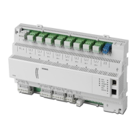
Product Description
The PXC Compact Series communicates with other field
panels or workstations on a peer-to-peer Automation
Level Network (ALN), or on the Field Level Network
(FLN), and supports the following communication
options:
• BACnet/IP or Ethernet TCP/IP over 10/100 MB
Ethernet networks
• RS-485 P2 or BACnet MS/TP on RS-485
networks
Required Tools and Materials
• Wire stripper/side cutter
• Small flat-blade screwdriver
• Phillips screwdriver
• Electric drill and Phillips driver bit
• Level
• Tape measure
• Digital multimeter (DMM)
• Black marker
• Masonry drill bit (to mount on concrete or
masonry)
• Four wall anchors (to mount on concrete or
masonry)
• Optional DIN rail (1.38" × 0.3" × 0.04" (35 mm ×
7.5 mm × 1 mm))
Included Materials
The following screws are included for mounting the PXC
Compact without a DIN rail:
• Four No. 8-18 × 3/8” self-tapping Phillips screws
• Four No. 8-18 × 3/4” self-drilling Phillips screws
• Two No. 8-18 × 1-3/4” self-drilling Phillips screws
Expected Installation Time
20 minutes
Prerequisites
No power wiring is connected to the field
panel controller or other TX-I/O
components at this time.
The TX-I/O island bus must be mounted on
a DIN rail (1.38" × 0.3" × 0.04" (35 mm ×
7.5 mm × 1 mm)).
• If mounting in an enclosure:
− Enclosure is installed, DIN rail included.
− The power source is installed, as applicable.
− The power is OFF.
• All necessary wiring is pulled and terminated per
the layout drawing.
• Power and communication wiring is terminated to
the removable plugs supplied with the devices.
CE Compliance Requirements
Must be installed inside a metal enclosure rated at IP20
minimum.
Energy Management Applications
For energy management only (low voltage Class 2), the
PXC Compact may be mounted on a flat surface.