EasyManua.ls Logo

Siemens QFA2000 User Manual

Siemens QFA2000
6 pages
To Next Page IconTo Next Page
Page #1 background imageLoading...
Page #1 background image
CE1N1857en
06.06.2005
Siemens Building Technologies
HVAC Products
1
857
Room Sensors
QFA20…
for relative humidity and temperature
Operating voltage AC 24 V or DC 13.5…35 V
Signal output DC 0...10 V for relative humidity
Signal output DC 0...10 V or LG-Ni 1000 or T1 for temperature
Accuracy of ± 3 % r.h. within comfort range
Range of use 15…+50 °C / 0…95 % r. h. (non-condensing)
Use
In ventilating and air conditioning plants to acquire
relative humidity and
temperature
in rooms.
The QFA20… is used as a
control sensor and
measuring sensor for building automation and control systems or indicating units.
Type summary
Type
reference
Temperature
measuring range
Temperature
signal output
Humidity
measuring range
Humidity
signal output
Operating voltage
QFA2000 None None 0...100 % Active, DC 0...10 V AC 24 V or DC 13.5…35 V
QFA2020 0...50 °C Passive, LG-Ni 1000 0...100 % Active, DC 0...10 V AC 24 V or DC 13.5…35 V
QFA2040 0...50 °C Passive, T1 0...100 % Active, DC 0...10 V AC 24 V or DC 13.5…35 V
QFA2060 0...50 °C / 35...+ 35 °C Active, DC 0...10 V 0...100 % Active, DC 0...10 V AC 24 V or DC 13.5…35 V
.
.
.
.
1857P01
Question and Answer IconNeed help?

Do you have a question about the Siemens QFA2000 and is the answer not in the manual?

Siemens QFA2000 Specifications

General IconGeneral
BrandSiemens
ModelQFA2000
CategoryAccessories
LanguageEnglish

Summary

Ordering

Equipment combinations

Details compatible systems and recommended signal converters for averaging passive sensors.

Mode of operation

Relative humidity

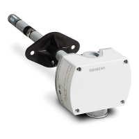
Sensor acquires relative humidity via capacitive element, converting to DC 0-10 V signal.

Temperature

Sensor acquires temperature via resistance element, outputting DC 0-10 V or passive signals.

Simulated passive output signal

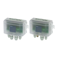
Electronic circuit compensates for self-heating impact on passive sensor resistance measurements.

Sensing elements, simulated

Provides graphs showing characteristics for simulated LG-Ni 1000 and T1 (PTC) sensing elements.

Mechanical design

Setting element

Test function activation

Describes using the shorting plug in vertical position to activate test function outputs.

Fault detection

Engineering notes

Cable routing and selection

Guidelines for cable routing, selection, interference, and using shielded/twisted pair cables.

Fitting notes

Specifies optimal location for sensor installation to ensure accurate readings.

Installation instructions

Notes on sealing conduits and finding instructions on the product packaging.

Commissioning notes

Technical data

Environmental conditions

Materials and colors

Standards

Internal diagram

Dimensions

Related product manuals