Document No. 129-416
Installation Instructions
October 5, 2009
Information in this publication is based on current specifications. The company reserves the right to make changes in specifications and
models as design improvements are introduced. Product or company names mentioned herein may be the trademarks of their respective
owners. © 2009 Siemens Industry, Inc.
Building Technologies Division
1000 Deerfield Parkway
Buffalo Grove, IL 60089
Your feedback is important to us. If you have comments
about this document, please send them to
SBT_technical.editor.us.sbt@siemens.com
Printed in the USA
Page 2 of 2
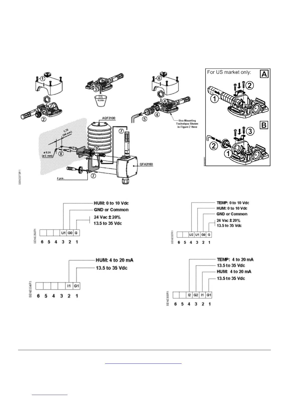
4. Connect the field wiring to the sensor terminal
block on the base. See Figures 3 and 4 for
wiring diagrams.
5. Install the sensor onto the Shield as shown. See
Figure 1 (7).
The installation is now complete.
Figure 1. Rh/T Outdoor Air Sensor Installation.
Figure 2. Field Wiring.
QFA3101
Figure 3. Wiring Diagrams for RH Sensors.
QFA3171/QFA4171
Figure 4. Wiring Diagrams for RH/T Sensors.