Mechanical design
The controller consists of 2 parts:
• Front panel which accommodates the electronics, the operating elements and the
built-in room temperature sensor
• Mounting base with the power electronics
The mounting base carries on the rear side the screw terminals. It fits on a rectangular
conduit box with fixing centres 60.3mm. The front panel engages in the mounting base
and snaps on.
1
2
4
5
6
7
8
9
10
11
12
13
14
15
6
3
3
3067Z04
5
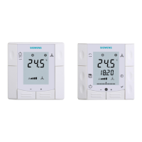
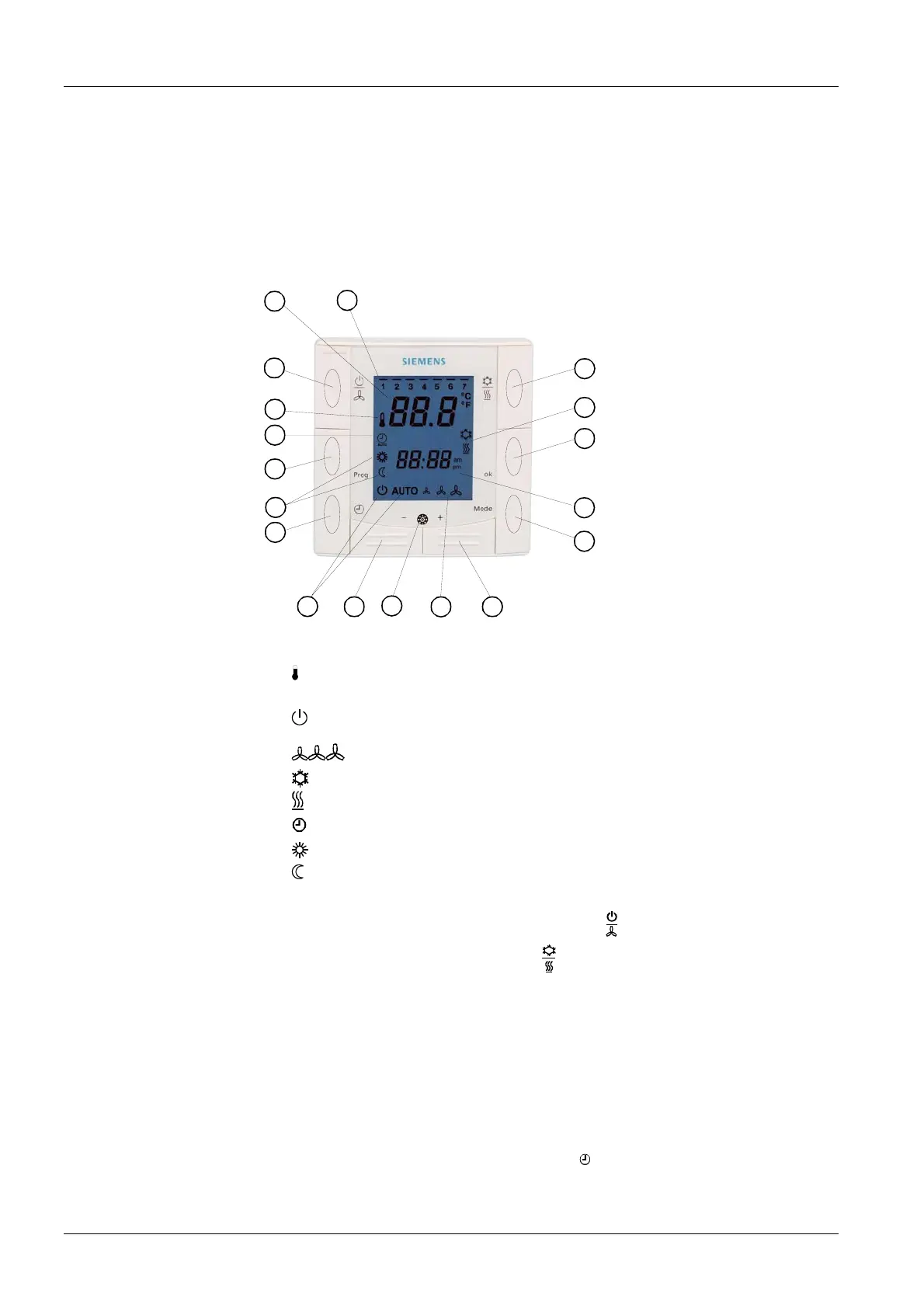
Setting and operating
elements
1 Display of the room temperature, setpoints and control parameters
Legend
2
Symbol used when displaying the current room temperature
3 Standby / fan mode status
Standby mode
AUTO Auto fan active
fan speed low, medium, high
4
in cooling mode
in heating mode
5
AUTO
Auto Timer mode
Normal operation
Energy Saving mode
6 Buttons for adjusting the setpoints, control parameters and time of day
7 Button for changing fan operation and Standby (
)
8 Manual heating / cooling changeover (
)
9 Infrared receiver (only with RDF310.21, RDF410.21)
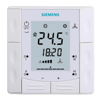
Only on RDF410...
10 Weekday 1..7 (1 = Monday / 7 = Sunday)
11 Current time of day
12 Auto timer program (
Prog)
13 Button operating mode (
Mode): Normal operation / Auto Timer mode
14 Button for setting time of day and weekday (
)
15 Confirmation (
ok)
10/14
Siemens Room Temperature Controllers N3067en
Building Technologies 01.10.2007
 Loading...