7/8
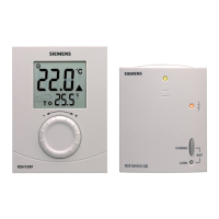
Siemens Building Technologies Room temperature controller REV100 CE1N2211en
Landis & Staefa Division 16.05.2000
• When installing the controller, the base must first be fitted and wired. Then, the unit
can be engaged at the top, swung downward and snapped on
• For more detailed information, refer to the installation instructions supplied with the
unit
• For the electrical installation, the local safety regulations and standards must be
complied with
• The remote control contact T1/T2 must be wired separately, using a shielded cable
• The battery transit tab, which prevents inadvertent operation of the unit during trans-
port and storage, must be removed
• The control characteristic can be changed with the DIP switch located at the rear of
the unit
• If the reference room is equipped with thermostatic radiator valves, they must be set
to the fully open position
• If the room temperature displayed does not agree with the measured temperature,
the sensor should be re-calibrated (refer to section "Calibration of sensor").
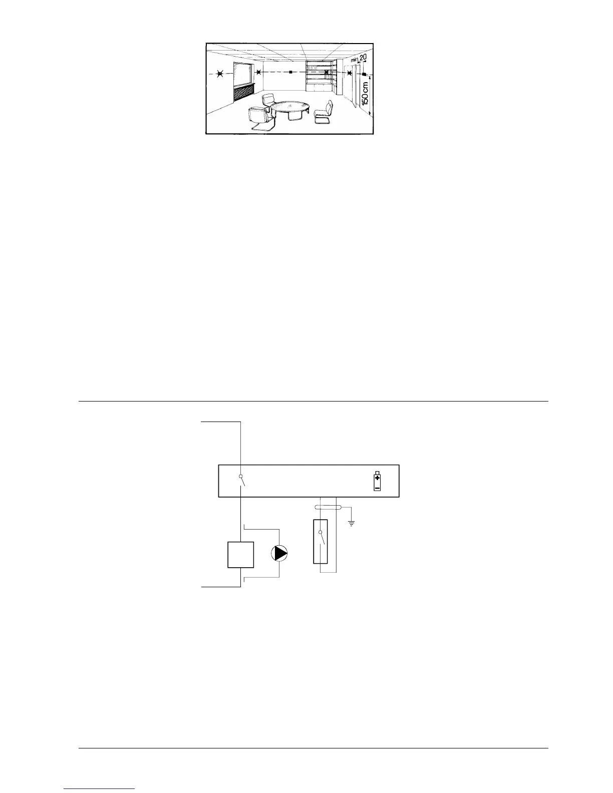
&RQQHFWLRQGLDJUDP
L
L1
Y1
M1
N1
N
S1
T1 T2
2211A01
A
C
2
4
.
.
.
2
5
0
V
DC 3 V
L Live, AC 24 ... 250 V S1 Remote operating unit (potential-free)
L1 N.O. contact, AC 24 ... 250 V / 8 (3.5) A T1 Remote control signal
M1 Circulating pump T2 Remote control signal
N1 REV100 controller Y1 Regulating unit
0RXQWLQJDQG
LQVWDOODWLRQ
&RPPLVVLRQLQJ