Press or
6 Finding the best place for reception
until the language you require appears.
Press
a) Switch on the RCR10/868
or move the slider to confirm the selected language
(also refer to Fig. G)
b) Set up the REV24RF.. at your preferred location.
Test the radio link by pressing the TEST button at the rear of
the controller (refer to Fig. N1)
3 Mounting the RCR10/868 temporarily
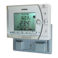
c) The display of the REV24RF.. shows the quality of the radio
link. The longer the bar below the numbers 0…9, the better the
quality of the radio link. If the bar only appears below number
0, there is no secure radio link (refer to operating instructions)
• If possible, mount the receiver temporarily (e.g. using double-
sided adhesive tape), thus allowing you to find the location
with the best reception conditions
• Wire completely the RCR10/868.
For steps to be followed, refer to Figs. H through M (close the
front also)
Insufficient Sufficient Good Very good
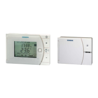
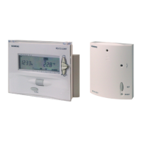
4 RCR10/868 and REV24RF..
d) On the receiver, LED_1 indicates the quality of the radio link
(refer to Fig. N2):
Red = insufficient or no connection
Orange = good
Green = very good
• The units are supplied interconnected
• For manual connection, refer to operating instructions
5 Mounting and setting up the
REV24RF..
e) If the quality of the radio link is insufficient, reduce the distance
between controller and receiver.
Then, repeat the test
• Refer to “Mounting instructions REV24RF.. and RCR10/868“
• Mount or set up the REV24RF.. at your preferred location:
Remove the unit from its baseplate; for procedure, refer to Fig.
A
- For wall mounting, refer to Figs. B, C and D
- For setting up, refer to Fig. E
7 Mounting the RCR10/868 in its final
place
a) Switch power off
b) Mark the place where the RCR10/868 is located
c) If necessary, remove wiring
d) Mount the receiver at the place previously identified (refer to
Figs. H through M), complete wiring and close the housing
e) Switch power on
Configuration and function check REV24RF..
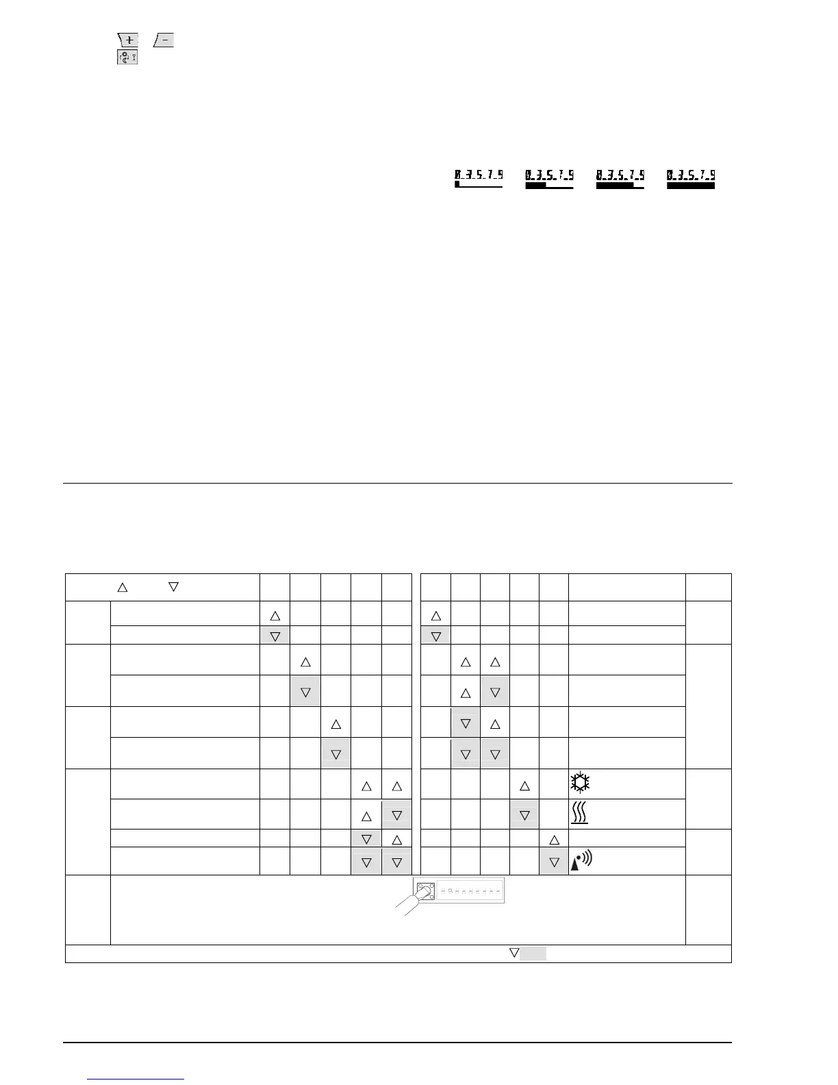
2 Configuration
1.2 DIP switches
ON / OFF 1 2 3 4 5 6 7 8 9 10
See
Sensor calibration on Periodic pump run on
See
1.1.1
1.1.5
Sensor calibration off
Periodic pump run off
Setpoint limitation
16…35 °C
Optimum start control:
1 h/°C
1.1.2
Setpoint limitation
3…35 °C
Optimum start control:
¼ h/°C
Temperature display °F
Optimum start control:
½ h/°C
1.1.6
1.1.3
Temperature display °C
Optimum start control:
Off
PID self-learning
(Cooling on)
1.1.7
PID 6
(Heating on)
PID12
Quartz
1.1.4
1.1.8
2-Point
Radio clock
ON
1
1.1.9
DIP switch reset
342
2211Z32
567 89
1.1.9
When changing one or several DIP switch positions, a DIP switch reset must be made by pressing the DIP switch reset
button (also refer to Fig. 8). Otherwise, the previous settings will be maintained!
Note: The factory setting of all DIP switches is OFF
8/29 13.12.2007 CE1G2206xx
 Loading...