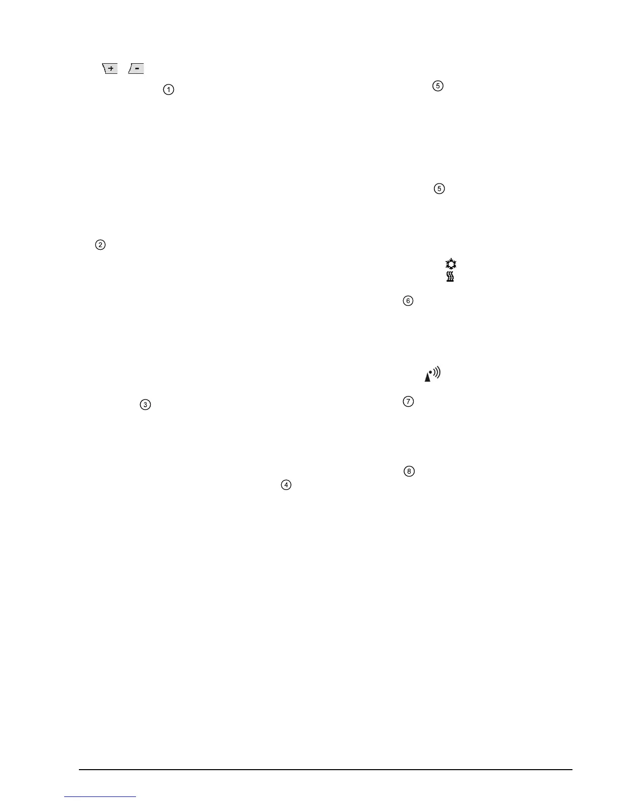
1.1.1 Sensor calibration: DIP switch 1 1.1.6 Optimum start control: DIP switches 7 and 8
Set the DIP switch to ON and press the DIP switch reset button:
The display shows CAL. The room temperature currently acquired
blinks.
Press
Optimum start control shifts switch on point P.1 such that the
adjusted setpoint will be reached at the required point in time. The
setting depends on the type of controlled system, that is, on heat
transmission (piping network, radiators), building dynamics (building
mass, insulation) and heat output (boiler output, flow temperature)
(also refer to graph in Fig.
or to make a recalibration of max. ± 5 °C. To save
the entry, set the DIP switch to OFF and press the DIP switch reset
button (also refer to Fig.
/ 1.1.6).
).
DIP switch 7 ON and 8 ON:
1 h/°C For slow controlled systems
1.1.2 Setpoint limitation: DIP switch 2
DIP switch 7 ON and 8 OFF:
¼ h/°C For fast controlled systems
DIP switch ON: Setpoint limitation 16…35 °C
DIP switch 7 OFF and 8 ON:
½ h/°C For medium controlled systems
DIP switch OFF: Setpoint limitation 3…35 °C
(factory setting)
DIP switch 7 OFF and 8 OFF:
OFF Off, no impact (factory setting)
Save the entry by pressing the DIP switch reset button.
Save the entry by pressing the DIP switch reset button.
1.1.3 Temperature display in °C or °F:
DIP switch 3
Legend to graph in Fig. .
.:
t Temperature (°C)
t Forward shift of switch on point (h)
TRx Actual value of room temperature
Pon Start point for optimum start control
DIP switch ON: Temperature display in °F
DIP switch OFF: Temperature display in °C
(factory setting)
Save the entry by pressing the DIP switch reset button (also refer to
Fig.
).
1.1.7 Heating or cooling mode: DIP switch 9
DIP switch 9 ON: Cooling
DIP switch 9 OFF:
1.1.4 Control action: DIP switches 4 and 5
Heating mode (factory setting)
DIP switch 4 ON and 5 ON: PID self-learning
Save the entry by pressing the DIP switch reset button
Adaptive control for all types of application.
DIP switch 4 ON and 5 OFF: PID 6
(also refer to Fig.
).
For fast controlled systems, applications at locations with
great temperature variations.
1.1.8 Radio clock: DIP switch 10
DIP switch 4 OFF and 5 ON: PID 12
For normal controlled systems, applications at locations
with normal temperature variations.
Can only be used if receiver DCF77 is integrated (time signal from
Frankfurt)!
DIP switch ON: Clock runs on built-in
quartz
DIP switch 4 OFF and 5 OFF: 2-Point
For difficult controlled systems, 2-position controller with
a switching differential of 0.5 °C (factory setting).
Time signal DCF77 from Frankfurt
DIP switch OFF:
Save the entry by pressing the DIP switch reset button
Save the entry by pressing the DIP switch reset button
(also refer to Fig.
).
1.1.5 Periodic pump run: DIP switch 6
Can only be used when circulating pump or valve is controlled!
This function protects the pump or valve against seizing during
longer off periods. Periodic pump run is activated for 3 minutes
every 24 hours at 12:00 (display showing symbol
▲).
DIP switch ON: Periodic pump run on (also refer to Fig.
)
DIP switch OFF: Periodic pump run off (factory setting)
Save the entry by pressing the DIP switch reset button.
(also refer to Fig.
).
1.1.9 DIP switch reset (Fig. )
When changing one or several DIP switch positions, press the DIP
switch reset knob to make a DIP switch reset.
Otherwise, the previous settings will be maintained!
(Also refer to Fig.
)
CE1G2206xx 13.12.2007 9/29
 Loading...