Siemens Building Technologies CE1G3333xx 07.01.2008 3/20
Bei Minimalbegrenzung: Bei Maximalbegrenzung:
Temperatur-Einstell-
schieber auf Maximalwert
stellen:
Regler muss die Tempera-
tur erhöhen (Heizventil
muss öffnen bzw. Kühl-
ventil muss schliessen)
Temperatur-Einstell-
schieber auf Minimalwert
stellen:
Regler muss die Tempera-
tur reduzieren (Heizventil
muss schliessen bzw.
Kühlventil muss öffnen)
► bei falscher Reaktion siehe Abschnitt «Fehler-
suche»
9. Betriebsspannung der Anlage ausschalten
10. Begrenzer auf Normalbetrieb umschalten (Schalter 5
auf
stellen)
11. Grenzwert am Temperatur-Einstellschieber einstellen
12. Deckel wieder montieren
Fehlersuche
Falsches Ergebnis Mögliche Ursachen
Ventil reagiert nicht
• Nicht angeschlossen
• Keine Betriebsspannung
Ventil läuft auf statt zu
oder
Ventil läuft zu statt auf
• Wirksinn falsch eingestellt
• Falsche Reglerklemme ver-
drahtet
Ventil bleibt in einer
Endlage stehen
Temperatur-Einstellschieber
steht auf EXT und es ist kein
Fernsollwertgeber angeschlos-
sen
Regelung reagiert zu
langsam
• P-Band tiefer einstellen
• Bei PI zusätzlich kürzere
Nachstellzeit wählen
Regelung ist instabil
• P-Band höher einstellen
• Bei PI zusätzlich längere
Nachstellzeit wählen
en English
Installation
Place of installation
Maximum permissible ambient temperature = 50 °C
• Flow temperature control:
− In the heating flow; immediately downstream from the
pump if pump is installed in the flow
− In the heating flow approximately 1.5...2 m down-
stream from the mixing point if pump is installed in the
return
• Return temperature control:
1...1.5 m downstream from the mixing point
• Minimum limitation of the boiler return temperature and
maximum limitation of the flow temperature:
1...1.5 m downstream from the mixing point
• D.h.w. temperature control:
1.5...2 m downstream from the mixing point
• Heat exchanger control:
As close as possible to the heat exchanger
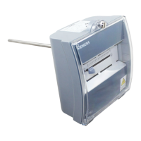
Mounting
The immersion temperature controller is designed for use
with threaded nipple:
Procedure:
1. Drain the piping system.
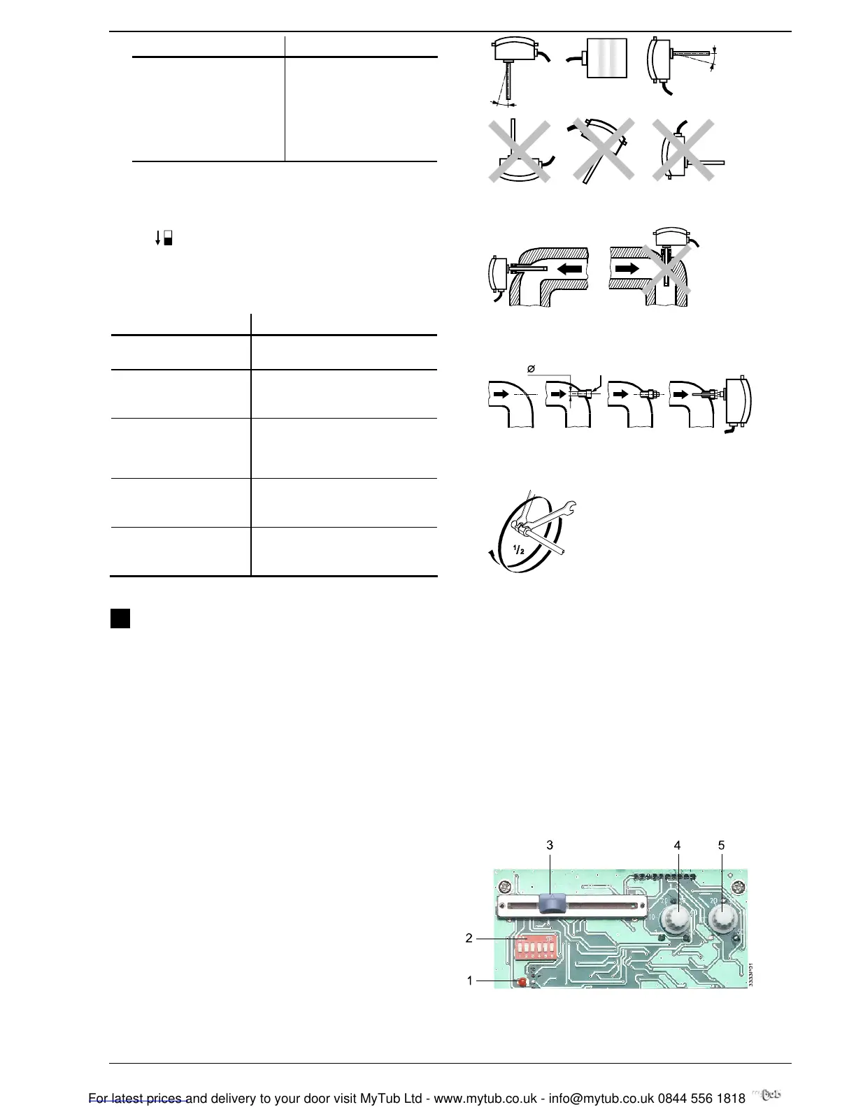
2. Choose one of the following mounting positions:
3333Z02
max. 15°
max. 15°
The controller may not be mounted upside down and the cable may not
enter from the top.
The minimum immersion length must be 60 mm.
3
3
3
3
Z
0
4
The controller should be mounted in a pipe bend with the sensor facing
the flow.
3. Use threaded sleeve:
G½
3333Z03
10 mm
4. Fit threaded nipple. If required, use sealing material
(hemp, Teflon tape, or similar).
5. Insert controller into the threaded nipple and fix:
1
3333Z06
6. Fill piping system again.
Electrical Installation
• Ensure that the local regulations for electrical installa-
tions are complied with
• The connecting terminals are located under the flexible
plastic cover
• Make wiring according to the plant documentation. If not
available, use the connection diagrams contained in
these Installation Instructions
• Observe the permissible cable lengths
• Switch on power only when commissioning the controller
Settings
1 LED for test mode / normal operation
2 DIP switch block
3 Setting slider for setpoint increase or decrease
4 Potentiometer for P-band Y2
5 Potentiometer for P-band Y1
 Loading...