Siemens Siemens
Siemens Siemens
Siemens
IndustryIndustry
IndustryIndustry
Industry
,,
,,
,
Inc. Inc.
Inc. Inc.
Inc.
Building Building
Building Building
Building
TT
TT
T
ecec
ecec
ec
hnologies Dihnologies Di
hnologies Dihnologies Di
hnologies Di
visionvision
visionvision
vision
P/N 315-033420-13
INTRODUCTION The Model RNI from Siemens Industry, Inc., allows for
the remote installation of the PMI/PMI-2/PMI-3, Global
PMI/PMI-2/PMI-3 (on XNET), SSD-C-REM (on HNET),
and the LVM/LCM-8/SCM-8/FCM-6/SIM-16/OCM-16
(on CAN) modules. When used in a REMBOX4, the
FMT and LVM are also supported.
The HNET/XNET can be wired either Style 4 or Style
7. The RNI must be placed in between two NIC-Cs
when used in a Style 7 Network with the Global PMI/
PMI-2/PMI-3 (on XNET) or the SSD-C-REM (HNET).
When using the PMI/PMI-2/PMI-3, the RNI may be
located in the middle or at the end of the HNET. Refer
to the table below for the allowable locations of
modules at the end of a HNET or XNET.
afodnEehttatnemecalPeludoM
krowteNTENXroTENH
TENHTENX
4elytS7elytS4elytS7elytS
MER-C-DSSYN**
3-IMP/2-IMP/IMP
)TENH(
YY* *
-IMP/IMPLABOLG
)TENX(3-IMP/2
**YN
krowtensihtnodewollatoN*,dewollA=Y,dewollatoN=N
The CAN network may only be wired Style 4. The RNI may be located at the end or in
the middle of a CAN network. A 24VDC input is also required. This can be obtained
from the PSC-12 power limited output (TB3) or any 24 VDC UL/ULC regulated, power
limited power supply listed for fire protective signaling use. Audio signals for the LVM
and FMT are connected to TB1 of the PSC-12.
The RNI mounts in the rear of either the REMBOX2 or REMBOX4 enclosures. It can
also be installed in a CAB1, CAB2, or CAB3 using the mounting plate RNI-CAB-BRKT.
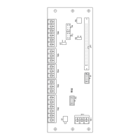
The RNI provides terminal blocks for all field wiring connections. Internal connections
are made to plug in connectors specifically provided for each of the installed modules.
The HNET/XNET and the CAN networks can be used simultaneously.
Remote Network Interface
Installation Instructions
Model RNI
X
H
24 V
TB1
P1
P3
P4
TB2
RNI
TB3
TB4
TB5
TB6
JP1
P6
S1
P5
P7
OFF
ON
P2
Figure 1
RNI Remote Network
Interface