Siemens Industry, Inc.
Building Technologies Division
P/N 315-033420-134
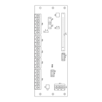
Figure 6
Connecting CAN In The Middle Of The Network
NOTES:
1. 18 AWG min., 14 AWG max.
2. 15 ohms max. for CAN
network.
3. Use twisted pair or twisted
shielded pair.
4. Power limited to NFPA 70
per NEC 760.
5. Refer to NIC-C Installation
Instructions, P/N 315-
033240 for connection of
CAN–, CAN+.
6. Only 1 SCM-8 shown.
SCM-8, LCM-8, FCM-6,
OCM-16, SIM-16 all allowed.
7. All field wiring supervised
8. Refer to PSC-12 Installation
Instructions, P/N 315-
033060 for ground fault
detection impedance.
1
4
3
6
4
1
3
6
P3 P4
CAN +
CAN –
CAN –
CAN +
SHIELD
SHIELD
FROM
PSC-12
TB1
TO NEXT
RNI
1
C+
2
C–
CCL*
CCL*
*ONLY 1 CCL, P/N 599-634214 IS SUPPLIED WITH THE RNI
3
S
4
C+
5
C–
6
S
RNI
TB6
1
2
3
4
5
6
7
8
9
0
1
2
3
4
5
6
7
8
9
0
LCM-8
OR
SCM-8
MOUNT TO ID-MP
ON INNER DOOR
OF REMBOX2/4
†
†
Figure 7
Connecting The LVM and FMT
NOTES:
1. 18 AWG min., 14 AWG max.
2. 15 ohms max. per pair.
3. Use twisted shielded pair for
LVM microphone and
monitor speaker.
4. Use twisted pair or twisted
shielded pair for phone.
5. Power limited to NFPA 70
per NEC 760.
6. Microphone and phone
circuits are supervised.
7. Monitor speaker is NOT
supervised.
8 Refer to LVM Installation
Instructions, P/N 315-034090.
9. Refer to FMT Installation
Instructions, P/N 315-034100.
10. No End Of Line devices
required.
11. Refer to PSC-12 Installation
Instructions, P/N 315-
033060 for ground fault
detection impedance.
 Loading...