Siemens Building Technologies CM2N3204E / 05.2001
Landis & Staefa Division 1/20
3
204
AEROGYR™
Controller
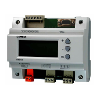
RWI65.02
for central air handling SW version 3.3
with single-speed or two-speed fans
Compact unit providing control and supervisory functions,
operating voltage AC 24 V, signal voltage DC 0...10 V.
Connection to Landis & Staefa building automation systems by means of
communication cards
In ventilating and air conditioning plants with
• hot water heating coils or electric air heater batteries
• direct expansion cooler batteries or chilled water cooling coils
• recirculated air dampers or heat recovery (HR) equipment
The RWI65.02 is used to:
• Control
– the room-supply air temperature or extract air-supply air temperature (cascade
control) with adjustable minimum and maximum limitations
– the room-supply air temperature or extract air-supply air temperature (cascade
control) with room or extract air-dependent shifting minimum and maximum
limitations (displacement ventilation)
– the supply air temperature
– the CO
2
/VOC content of the room air (demand-controlled ventilation)
– single- or two-speed fans
– air coolers
– chillers
– HR equipment
– hot water heating coils (with preheating)
– electric air heater batteries (with fan overrun)
– circulators in hot or chilled water circuits (load- or outside temperature-dependent)
– air damper actuators (with recirculated start-up circuit for modulating dampers)
– regulating units in hot and chilled water circuits
.
.
.
.
Use