Siemens Building Technologies CM2N3204E / 05.2001
Landis & Staefa Division 15/20
Wiring diagram 6 and 7: Measuring element with CO
2
/VOC sensor with or without
ventilation demand processor for demand-controlled ventilation
G
G
G0
U
G0
U1M
AC 24 V
U2
G
(CO
2
)
(VOC)
U1
M
B7
G
G0
G1 U2
S
M Z
N1
3204A09
10
U3
M
D
G
G
3204A10
G0
N1
G0
U1M
AC 24 V
U2
G
(CO
2
)
(VOC)
ZM
B7
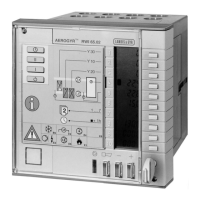
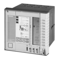
N1 Controller RWI65.02
N2 RVL55 with plug-in module AZY55.60
B1 Room or extract air temperature sensor QAA24/QAM22...
B2 Supply air temperature sensor QAM22...
B3 Outside temperature sensor QAM22.../QAC22
B4 Temperature sensor QAD22/QAE21.9...
B5 Frost sensor QAF63.2/QAF63.6
B6 Extract air temperature sensor QAM22...
B7 CO
2
/VOC sensor QPA63...
R1 Remote setting unit FZA61.11
R2 Room unit QAA26 or setpoint transmitter FZA21.21
S On/Off switch "Locking signal"
U Ventilation demand processor AQP63.1
Wiring diagram 8: Control part with regulating units for heating, cooling and HR
G
G
G0 Y10
GY
G0
Y20 Y30
G0
N1
Y1 Y2 Y3
3204A05
AC 24 V
GGGG0G0G0
GY
G0
GY
G0
N1 Controller RWI65.02
Y1 Regulating unit for heating
Y2 Regulating unit for cooling
Y3 Regulating unit for HR/recirculated air dampers
Wiring diagram 9:
GE E1 E2 E3 E4 E5 E6
Q44
Q13 Q33
Q34
3204A06
T
Dp
F91
L
H1 K3 K4
N1
AC 230 V
AC 24 V
F3
F3
Auto
0
I
II
E7 E8
Q24
F2
Q14
F1
K2
K1
S1
G
G0
F2F1
N
G
G0
K4
K3
F4
F4
N1 Controller RWI65.02
F1...F4 Overload relay contact
H1 Auxiliary unit for common fault signal
K1 Motor contactor for hot water pump or contactor for electric heater battery
K2 Motor contactor for chilled water circulator or chiller
K3 Motor contactor for fan speed I
K4 Motor contactor for fan speed II
Legend for wiring
diagrams 1 to 7
Connections on the
control side
Legend
Connections on the
control and
supervision side
Legend
 Loading...
