Description
7
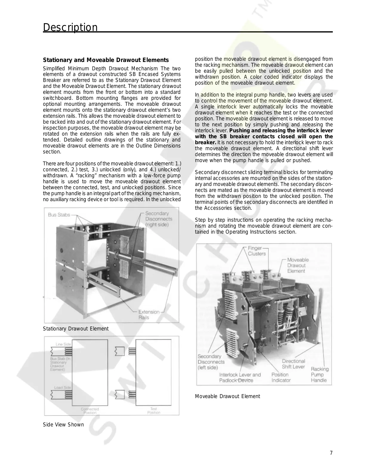
Stationary and Moveable Drawout Elements
Simplified Minimum Depth Drawout Mechanism The two
elements of a drawout constructed SB Encased Systems
Breaker are referred to as the Stationary Drawout Element
and the Moveable Drawout Element. The stationary drawout
element mounts from the front or bottom into a standard
switchboard. Bottom mounting flanges are provided for
optional mounting arrangements. The moveable drawout
element mounts onto the stationary drawout element’s two
extension rails. This allows the moveable drawout element to
be racked into and out of the stationary drawout element. For
inspection purposes, the moveable drawout element may be
rotated on the extension rails when the rails are fully ex-
tended. Detailed outline drawings of the stationary and
moveable drawout elements are in the Outline Dimensions
section.
There are four positions of the moveable drawout element: 1.)
connected, 2.) test, 3.) unlocked (only), and 4.) unlocked/
withdrawn. A “racking” mechanism with a low-force pump
handle is used to move the moveable drawout element
between the connected, test, and unlocked positions. Since
the pump handle is an integral part of the racking mechanism,
no auxiliary racking device or tool is required. In the unlocked
position the moveable drawout element is disengaged from
the racking mechanism. The moveable drawout element can
be easily pulled between the unlocked position and the
withdrawn position. A color coded indicator displays the
position of the moveable drawout element.
In addition to the integral pump handle, two levers are used
to control the movement of the moveable drawout element.
A single interlock lever automatically locks the moveable
drawout element when it reaches the test or the connected
position. The moveable drawout element is released to move
to the next position by simply pushing and releasing the
interlock lever. Pushing and releasing the interlock lever
with the SB breaker contacts closed will open the
breaker. It is not necessary to hold the interlock lever to rack
the moveable drawout element. A directional shift lever
determines the direction the moveable drawout element will
move when the pump handle is pulled or pushed.
Secondary disconnect sliding terminal blocks for terminating
internal accessories are mounted on the sides of the station-
ary and moveable drawout elements. The secondary discon-
nects are mated as the moveable drawout element is moved
from the withdrawn position to the unlocked position. The
terminal points of the secondary disconnects are identified in
the Accessories section.
Step by step instructions on operating the racking mecha-
nism and rotating the moveable drawout element are con-
tained in the Operating Instructions section.
Stationary Drawout Element
Side View Shown
Moveable Drawout Element
Courtesy of NationalSwitchgear.com