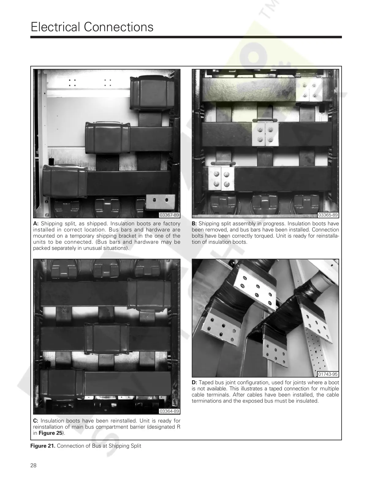
Figure 21. Connection of Bus at Shipping Split
Electrical Connections
28
A: Shipping split, as shipped. Insulation boots are factory
installed in correct location. Bus bars and hardware are
mounted on a temporary shipping bracket in the one of the
units to be connected. (Bus bars and hardware may be
packed separately in unusual situations).
B: Shipping split assembly in progress. Insulation boots have
been removed, and bus bars have been installed. Connection
bolts have been correctly torqued. Unit is ready for reinstalla-
tion of insulation boots.
C: Insulation boots have been reinstalled. Unit is ready for
reinstallation of main bus compartment barrier (designated R
in Figure 25).
D: Taped bus joint configuration, used for joints where a boot
is not available. This illustrates a taped connection for multiple
cable terminals. After cables have been installed, the cable
terminations and the exposed bus must be insulated.
03367-89 03365-89
03364-89
01743-95
Courtesy of NationalSwitchgear.com
 Loading...