66 SSeettuupp aanndd OOppeerraattiioonn
6.1 Setup Controls
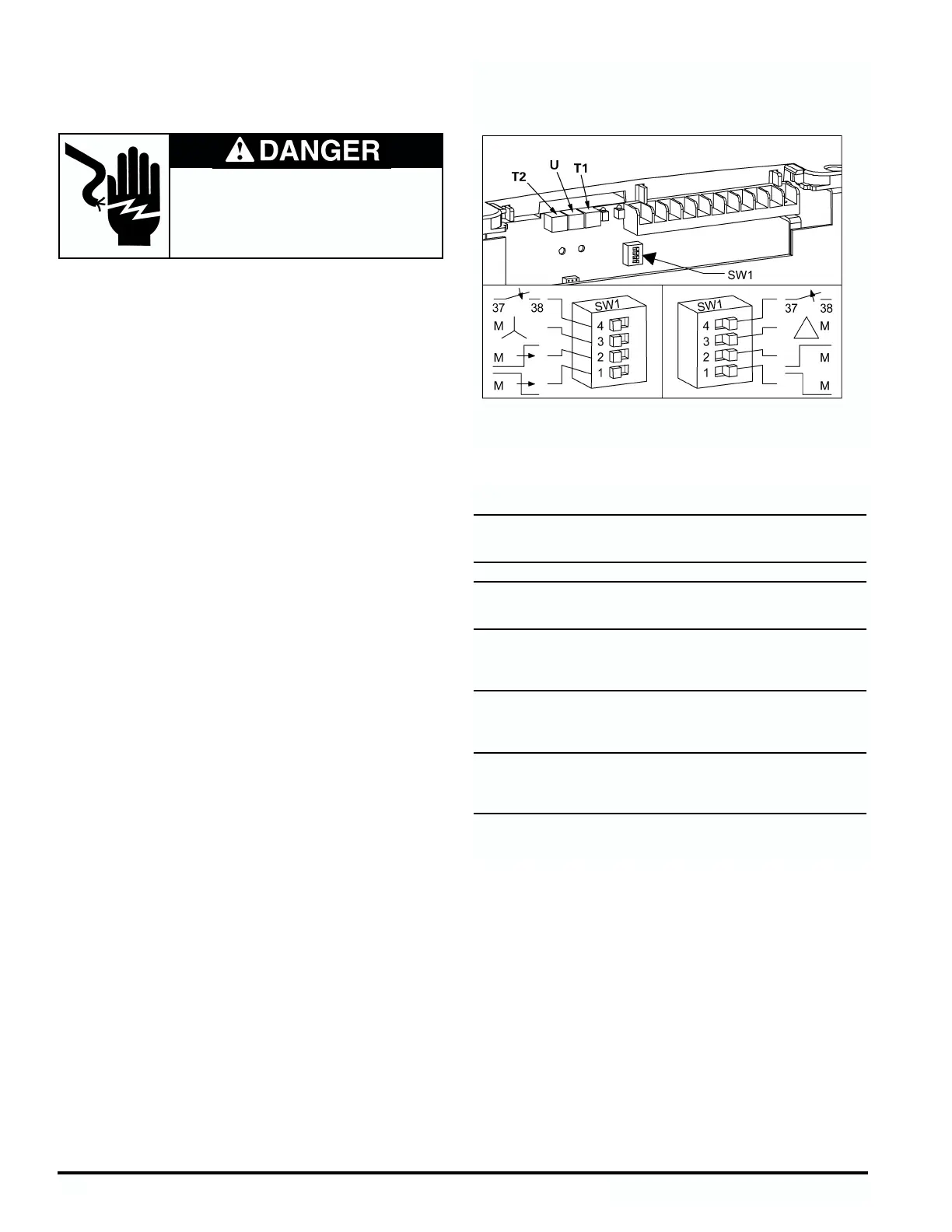
The setup controls are at the right side of the controller and are
accessible without removing the cover. Figure 20 shows the
controls: three potentiometers, T1, U, and T2; and DIP switch
SW1. Values for the potentiometer settings are listed in Table 6.
Use a small screwdriver to change the potentiometer setting,
rotating clockwise to increase and counterclockwise to
decrease.
Note: The controls are set at the factory for a typical starter.
Please verify the application for proper settings.
T1 - Start Time. This 16-position potentiometer sets the accel-
eration ramp time up to 60 seconds maximum. This setting
determines the time interval for the voltage to increase from the
initial setting (U) to line voltage. The factory settings is 8.
U - Initial Voltage. This 16-position potentiometer sets the ini-
tial voltage at a percentage of line voltage: 30% to 80%. The ini-
tial setting should be the level that causes the motor shaft to
turn as soon as the run signal is given. The factory setting is
8.
T2 - Stop Time. This 16-position potentiometer sets the decel-
eration ramp time up to 60 seconds maximum. This setting
determines the time interval for the voltage to decrease from
line voltage to 80% of the initial setting (U).The “0” dial position
allows the motor to coast to a stop. The factory setting is 0.
SW1 - DIP Switch. This switch has four sections which provide
setting the controller software to correspond to the application.
Each switch section is positioned by sliding it to the right or left
as viewed in figure 20 (up or down when the controller is
mounted vertically). On the wiring diagrams in section 5, the
position of each switch section is indicated by an arrow pointing
to either the right or left.
1. SW1-1: This switch provides a turn off delay signal setting
(left position). The off delay allows a bypass contactor to de-
energize 1.5 seconds before the controller RUN coil de-ener-
gizes. This delay eliminates damage to the SCRs caused by
voltage transients produced when the bypass contactor
interrupts motor current.
The right position of switch SW1-1 provides no delay. When
the stop device is actuated, the RUN coil de-energizes
immediately.
2. SW1-2: This switch provides a turn on delay signal setting
(left position). The on delay allows an isolation contactor to
energize first, at zero current, followed by the controller RUN
coil 1.5 seconds later. The delay maximizes contact life on
the isolation contactor.The right position of switch SW1-2
provides no delay. When the start device is actuated, the
RUN coil energizes immediately.
3. SW1-3: This switch directs the controller software to oper-
ate the SCRs for either a Wye motor - In Line wiring (left
position) or a Star/Delta motor - Inside Delta wiring (right
position).
4. SW1-4: This switch sets the fault contact, which is a nor-
mally open contact,to respond to a fault by either closing
(arrow down position, switch to the left) or opening (arrow
up position, switch to the right).
Siemens Energy & Automation, Inc.
28
Hazardous voltage.
Will cause death or serious injury.
To avoid electrical shock or burn, turn off
main and control voltages before performing
installation or maintenance.
Figure 20 - Setup Controls
Table 6 - Potentiometer Setting Values
Ramp Time
Dial Initial Voltage U T1, T2
Setting (% Full Voltage) (Seconds)
030 0.5
133 1.0
236 2.0
340 4.0
443 6.0
546 8.0
650 10
753 12
856 15
960 20
A63 25
B66 30
C70 35
D73 40
E76 50
F80 60
Factory Settings T1=8 (15 sec)
T2=0 (.5 sec)
V=8 (56%)

 Loading...