EasyManuals Logo

Siemens SIMATIC 500 Series User Manual

Siemens SIMATIC 500 Series
47 pages
To Next Page IconTo Next Page
To Previous Page IconTo Previous Page
Page #23 background imageLoading...
Page #23 background image
4 Setting Up
16
Version 2.1 10/01
4.2 General information about setting up
+24 VDC
+24 VDC *
Fault
L1+
L2+
M
F1
F2
NEC Class 2 24VDC, 200mA
01
S 6
S 7
S 1
S 0
S 2
S 4
S 5
S 3
Out. Power CH 3
Compatibility
Out. Power CH 2
Mode CH 1
Mode CH 2
Mode CH 3
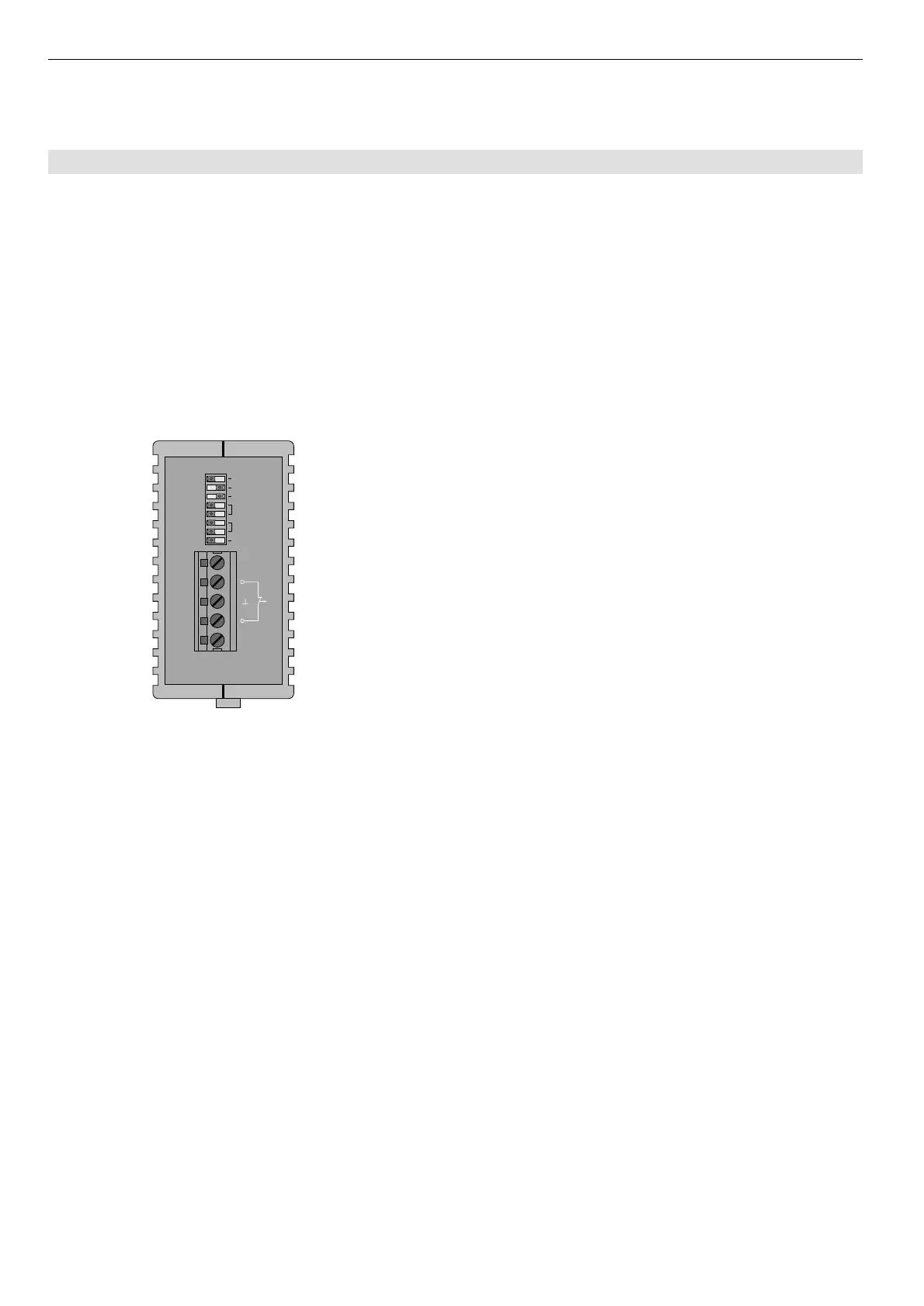
Fig. 5: Top view of the Module OLM – location of the DIL
switches and terminal block for the operating power
supply/signaling contacts.
The illustration shows the factory settings of the
DIL switches (switches S0, S1, S2, S3, S4 and S7 in
Position "0", switches S5 and S6 in Position "1").
Select the network topology which is most suitable for your requirements. The modules can then be put into
operation in the following steps:
Check and adjust (if necessary) the DIL switch
Note: The DIL switches may only be operated in an ambient temperature of between 0°C and +60°C. This also
applies to the OLM/G12-EEC.
Mount the modules
Connect the power supply and the signaling contacts
Connect the electric RS 485 bus line with pre-mounted bus connector
Connect the optical bus lines

Questions and Answers:

Question and Answer IconNeed help?

Do you have a question about the Siemens SIMATIC 500 Series and is the answer not in the manual?

Siemens SIMATIC 500 Series Specifications

General IconGeneral
Protection ClassIP20
SeriesSIMATIC
CPU Types505
Communication ProtocolsPROFIBUS
Power Supply24V DC
I/O ModulesDigital Input/Output, Analog Input/Output
Operating Temperature0°C to 60°C
Product FamilySIMATIC 500
Inputs/OutputsScalable, depending on the number and type of I/O modules

Related product manuals