Optional customer keys X53/X54
The outputs X53 / X54 are intended to activate lamps in the keys.
We would recommend using 1.2 W lamps with max. 0.3 A per output.
High-side switches which switch 24 V to the lamps and limit the current during short circuits
are used as output drivers.
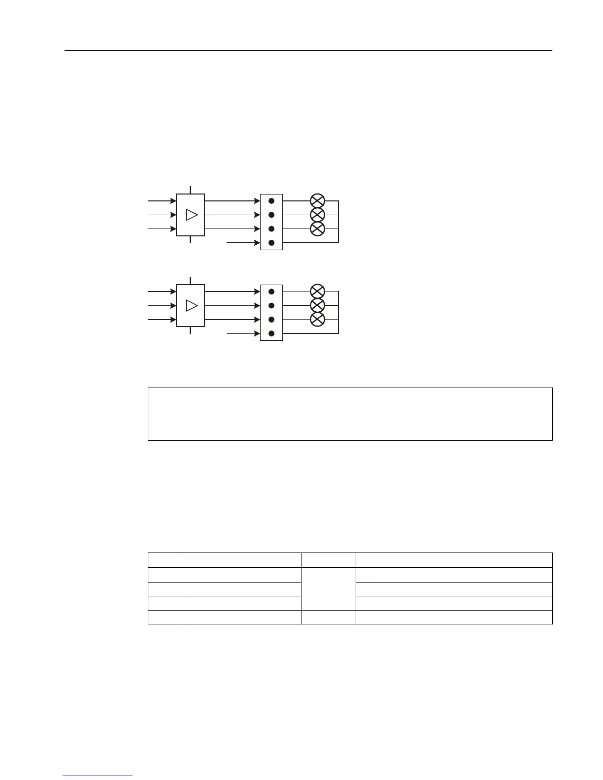
Figure 4-7 Schematic circuit diagram of the output circuit for X53 and X54
NOTICE
Damage to the module through induction voltages
Do not connect any relays, valves or other inductive loads.
Interface: Optional customer keys OUT
Connector designation: X53/X54
Connector type: 4-pin male connector
Table 4-11 Assignment of connector X53
Pin Name Type Meaning
1 KT-OUT1
O
Customer key 1 lamp
2 KT-OUT2 Customer key 2 lamp
3 KT-OUT3 Customer key 3 lamp
4 M V Ground
Interfaces
4.3 Machine control panels
ERGOline Stage 3
Manual, 02/2015, 6FC5397-4FP40-0BA0 29

 Loading...


