SIMATIC IFP2200/2400 ITC2200/2400 frameless
20 A5E48015893-AC, 03/2021
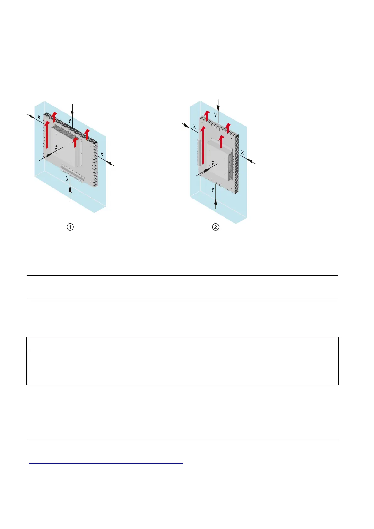
Required clearance
The following clearance is required for sufficient self-ventilation around the device:
• At least 10 mm to the right and left of the mounting cutout (in x direction)
• At least 10 m above and below the mounting cutout (in y direction)
• At least 10 mm behind the rear panel of the device (in z direction).
The figure below shows the required clearances when the device is installed in landscape and portrait format:
Clearance for mounting in landscape format
Clearance for mounting in portrait format
Note
Ensure that the permitted ambient temperature is not exceeded when mounting the device in a cabinet and especially in a
closed enclosure.
Mounting the device
Installation guidelines
Damage to the device due to the open front
The frameless front does not have a protective enclosure. Electrostatic-sensitive components are destroyed on contact with
wires. The front can warp when shear forces are applied. This can result in damage to the machine or system.
• Observe the safety information on ESD guidelines.
• Do not expose the front to mechanical stress, e.g. during installation.
• Ensure adequate sealing during installation.
• Higher degrees of protection of the device front can only be guaranteed if the mounting seal is intact and lies flush
against the mounting cut-out.
• To guarantee a higher degree of protection, you need to take suitable measures yourself. With correct installation, IP65
can be reached.
• Observe the minimum thickness of the enclosure (material thickness): Height of threaded sleeve = 5.5 mm.
• Observe the length of the M3 screws: Maximum screw-in depth into threaded sleeve = 5 mm.
data for electrical planning (circuit diagrams, data sheets, ePlan macros), for example, are available from the
underlying standard devices. A description of how to obtain this data can be found on the Internet: CAx Download
(https://support.industry.siemens.com/cs/us/en/view/89671877)
 Loading...