Do you have a question about the Siemens RD150 and is the answer not in the manual?
Manual provides instructions for mounting, connection, setup, maintenance, fault rectification, part exchange, and user safety.
Manual is for trained personnel and explains symbols used for warnings, information, and procedures.
Operations by trained personnel; RD150 is for 4-20mA/HART sensors; hazards of incorrect use.
Instrument must be flawless; operator responsible for safe operation and rule compliance.
Device fulfills EU directives (CE marking) and NAMUR recommendations NE 21 & NE 53.
Details the type label, instrument versions, and scope of delivery.
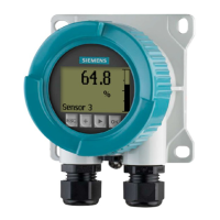
Explains RD150's function for measured value indication and adjustment of HART sensors.
Guidelines for packaging, transport, inspection, and storage conditions to prevent device damage.
Covers installation position, protection against moisture, and housing lid closure.
Details wall, carrier rail, tube, and front panel mounting procedures with specific dimensions.
Safety instructions for electrical connection, voltage supply, and cable requirements.
Explains connection steps, terminals, and provides various wiring plans for different configurations.
Describes the display module's purpose, installation, and key functions for indication and adjustment.
Guides users through setting measurement loop name, damping, scaling, and display options.
Guides users through adjusting sensor parameters like TAG, PV unit, range, and damping using HART.
Describes connecting the PC and using PACTware software with DTMs for parameter adjustment.
Recommends documenting or saving parameterisation data via PACTware for reuse and service.
No special maintenance required; guidelines for cleaning the instrument.
Explains sensor self-monitoring, error codes, causes, rectification, and troubleshooting the 4-20 mA signal.
Details components for software updates and instructions for instrument repair.
Presents detailed specifications: materials, weights, operating voltage, current range, ambient conditions, and electrical protection.
Explains the HART protocol and lists supported HART commands for sensor communication.
Provides physical dimensions for RD150 in various housing types and mounting configurations.
States that all brands and trade names are property of their respective owners.
| Resolution | 1024 x 768 pixels |
|---|---|
| Viewing Angle | 160° horizontal, 160° vertical |
| Input Voltage | 24 V DC |
| Display Type | TFT LCD |
| Display Size | 15 inches |
| Operating Temperature | 0 to 50 °C |
| Protection Class | IP65 |
| Storage Temperature | -20 to 60 °C |
| Shock Resistance | 15 G |
| Mounting | VESA Mount |
| Certifications | CE, UL |