18
MAN-100472RD150 - Operating Instructions
57030-EN-180717
5.3 Wiring plan
Sensor
1
2
+
( )
(-)
power supply
3
4
+
( )
(-)
R
off
on
HART
1
4
2
3
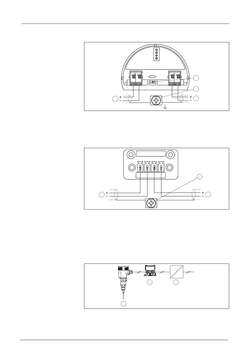
Fig. 10: Wiring plan RD150 4 … 20 mA/HART
1 To the sensor
2 Switchforcommunicationresistor(on=activated,o=deactivated)
3 Terminal for connection of the cable screen
4 For power supply
1
3
2
4
3
1
2
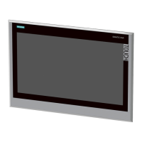
Fig. 11: Wiring plan RD150 for 4 … 20 mA sensors - panel mounting
1 To the sensor
2 Ground terminal in the switching cabinet for connection of the cable screen
3 For power supply
5.4 Connection HART standard
ThefollowingillustrationshowsinasimpliedwaytheuseofRD150
in conjunction with a HART sensor.
~
=
1
2
3
Fig. 12: Installation example RD150 in conjunction with an individual sensor
1 Sensor
2 RD150
3 Voltage supply/Processing
Wiring plan
Wiring plan - Panel
mounting