9
MAN-100472 RD150 - Operating Instructions
57030-EN-180717
3.2 Principle of operation
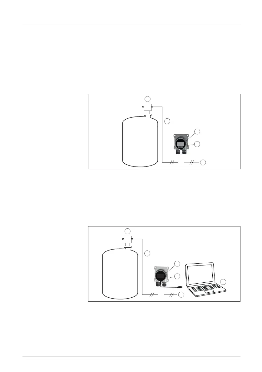
RD150 is suitable for measured value indication and adjustment of
sensors with HART protocol. The instrument is looped directly into
the 4 … 20 mA HART signal line at any location. Separate external
energy is not necessary. RD150 also operates exclusively as an
indicating instrument in a 4 … 20 mA current loop.
The sensor adjustment is carried out in the RD150 integrated in the
display and adjustment module.
4
5
3
1
2
Fig. 2: Connection of the RD150 to the sensor, adjustment via the display and
adjustment module
1 Voltage supply/Signal output sensor
2 RD150
3 Display and adjustment module
4 4 … 20 mA/HART signal cable
5 Sensor
The sensor adjustment is carried out via a PC with PACTware/DTM.
4
5
6
3
2
1
Fig. 3: Connection of the RD150 to the sensor and the PC, adjustment via PC
with PACTware
1 Voltage supply/Signal output sensor
2 RD150
3 Interface adapter
4 4 … 20 mA/HART signal cable
5 Sensor
6 PC with PACTware/DTM
Application area
Sensor adjustment
Sensor adjustment via PC
with PACTware