20
MAN-100472RD150 - Operating Instructions
57030-EN-180717
3
1
2
Sensor
1
2
+
( )
(-)
power supply
3
4
+
( )
(-)
R
+
-
off
on
HART
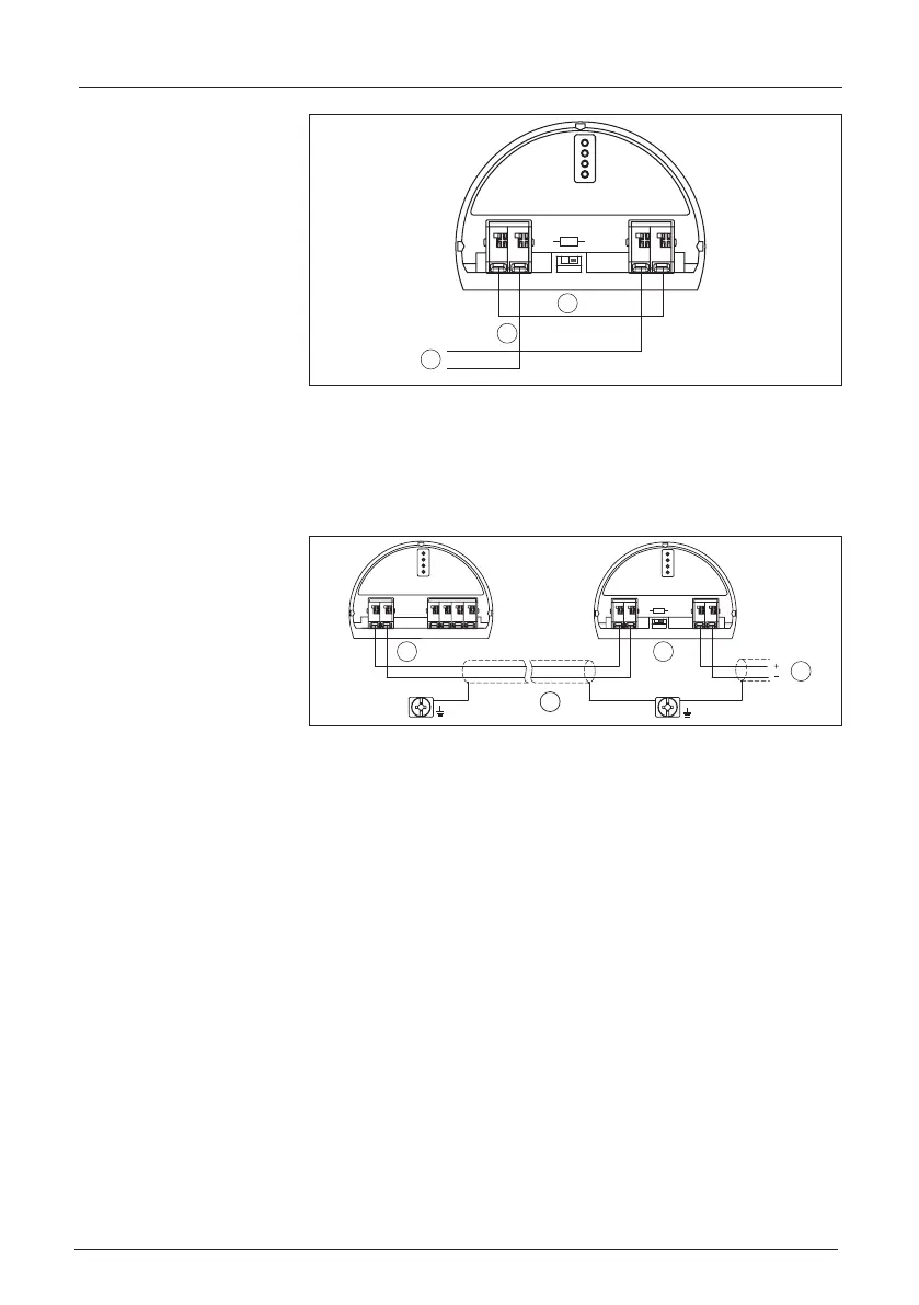
Fig. 14: Bridge between terminals 1 and 4 on the RD150
1 Bridge
2 RD150
3 Active sensor
5.7 Connection example
1
3
24
5
1
2
+
( )
(-)
678
4...20mA
Sensor
1
2
+
( )
(-)
power supply
3
4
+
( )
(-)
R
off
on
HART
Fig. 15: Connection example 4 … 20 mA/HART
1 Voltage supply
2 RD150
3 Connection cable
4 Sensor
5.8 Switch-on phase
After connecting the instrument to power supply or after a voltage
recurrence, the instrument carries out a self-check for approx. 10 s:
•
Internal check of the electronics
•
Indication of the instrument type, hardware and software version,
measurement loop name on the display or PC
•
Indication of a status message on the display or PC
The duration of the warm-up phase depends on the connected sen-
sor.
Thentheactualmeasuredvalueisdisplayed.Youcanndfurther
information on the display in chapter "Measured value indication -
Selection national language".