32
MAN-100472RD150 - Operating Instructions
57030-EN-180717
1
3
6
5
2
4
Sensor
1
2
+
( )
(-)
power supply
3
4
+
( )
(-)
R
off
on
HART
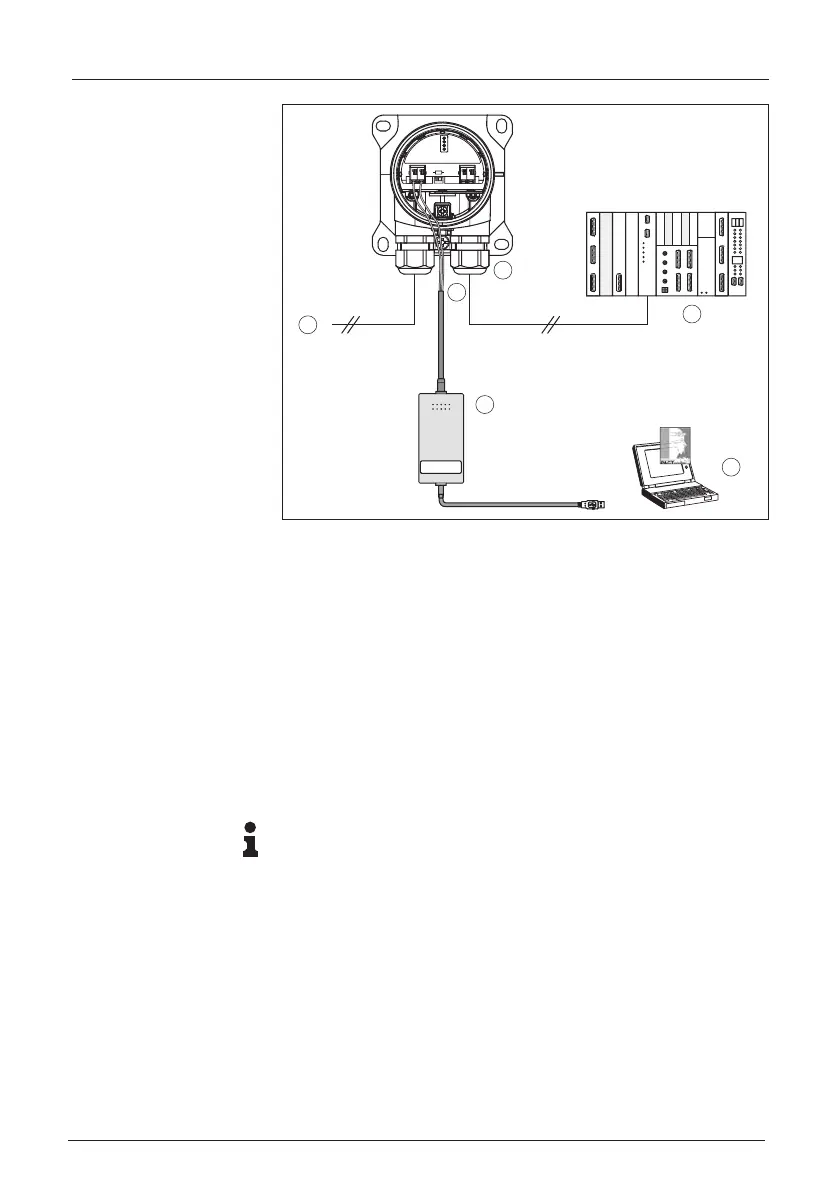
Fig. 19: Connecting the PC via HART to the signal cable
1 Processing system/PLC/Voltage supply
2 RD150
3 To the sensor
4 Connection cable with 2 mm pins and terminals
5 HART modem
6 PC
7.2 Parameter adjustment with PACTware
For parameter adjustment of the sensor via a Windows PC, the
congurationsoftwarePACTwareandasuitableinstrumentdriver
(DTM) according to FDT standard are required. The available DTMs
are compiled on a DVD. The DTMs can also be integrated into other
frame applications according to FDT standard.
Note:
To ensure that all instrument functions are supported, you should
always use the latest DTM. Furthermore, not all described functions
areincludedinolderrmwareversions.Youcandownloadthelatest
instrument software from our homepage. A description of the update
procedure is also available in the Internet.
The further setup steps are described in the online help of PACTware
and the DTMs.
Prerequisites