SIMATIC IFP2200/2400 ITC2200/2400 frameless
22 A5E48015893-AC, 03/2021
Note
Equipotential bonding cable
Cable shields are not suitable for equipotential bonding. Always use the prescribed equipotential bonding conductors for this.
An equipotential
-bonding cable between control cabinets or housings in general must have a minimum conductor cross-
section of 16 mm². The cable between the ground bar and device must have a minimum conductor cross-section of 4 mm
2
Wiring diagram
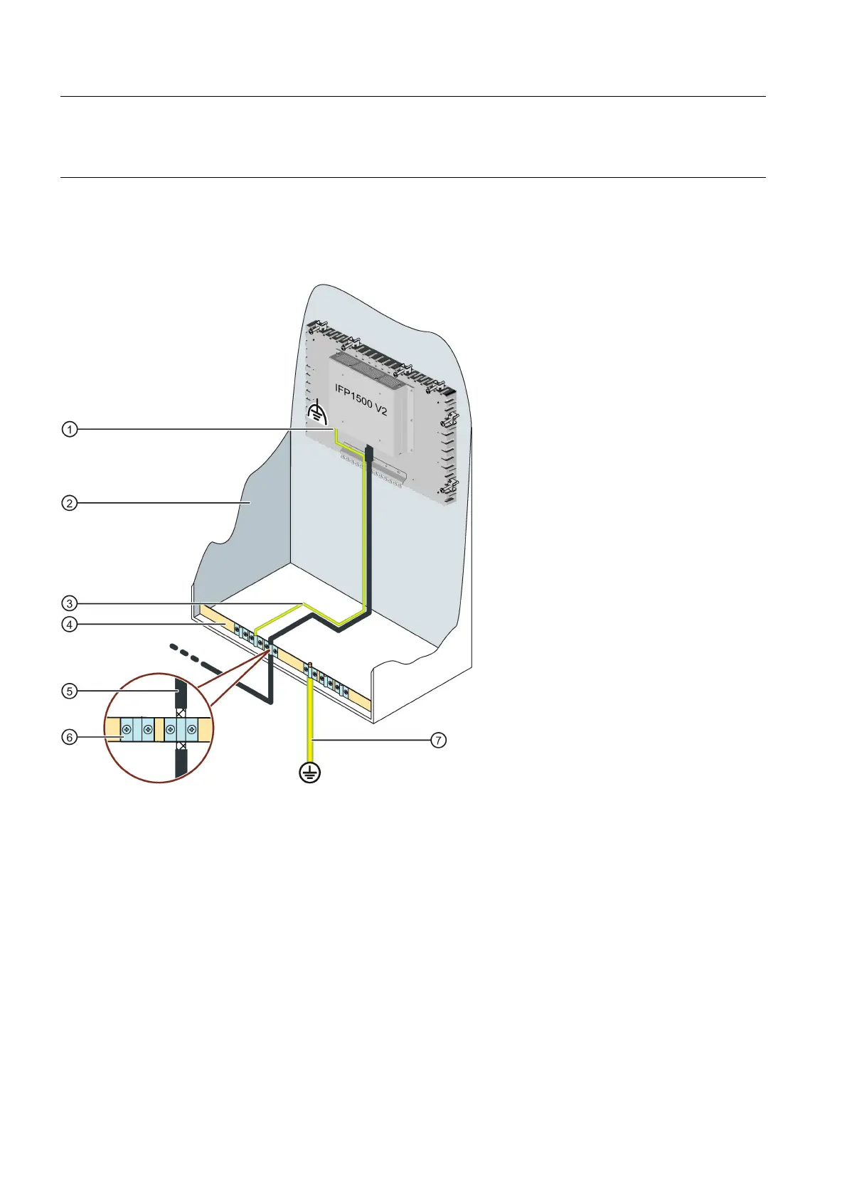
The following figure shows the connection of the functional ground for the equipotential bonding as an example and applies
in the same way to all devices, including the IFP Transceiver Unit. In the figure the control cabinet is only one example for an
enclosure.
Connection for functional ground
Control cabinet / housing
Equipotential bonding cable, 4 mm
2
Equipotential busbar for equipotential bonding cables, grounding connection and shield support of the data cables, for
example, in extended operation
Data cable, e.g. PROFINET or for IFP devices for Transceiver Unit in extended operation
2
 Loading...