Connection system in IP65/67
M12 connectors and other connectors are defined for the connection system in IP65/67;
sensors have a 4-pin connector, actuators a 5-pin connector. IO-Link masters are always
equipped with a 5-pin M12 socket.
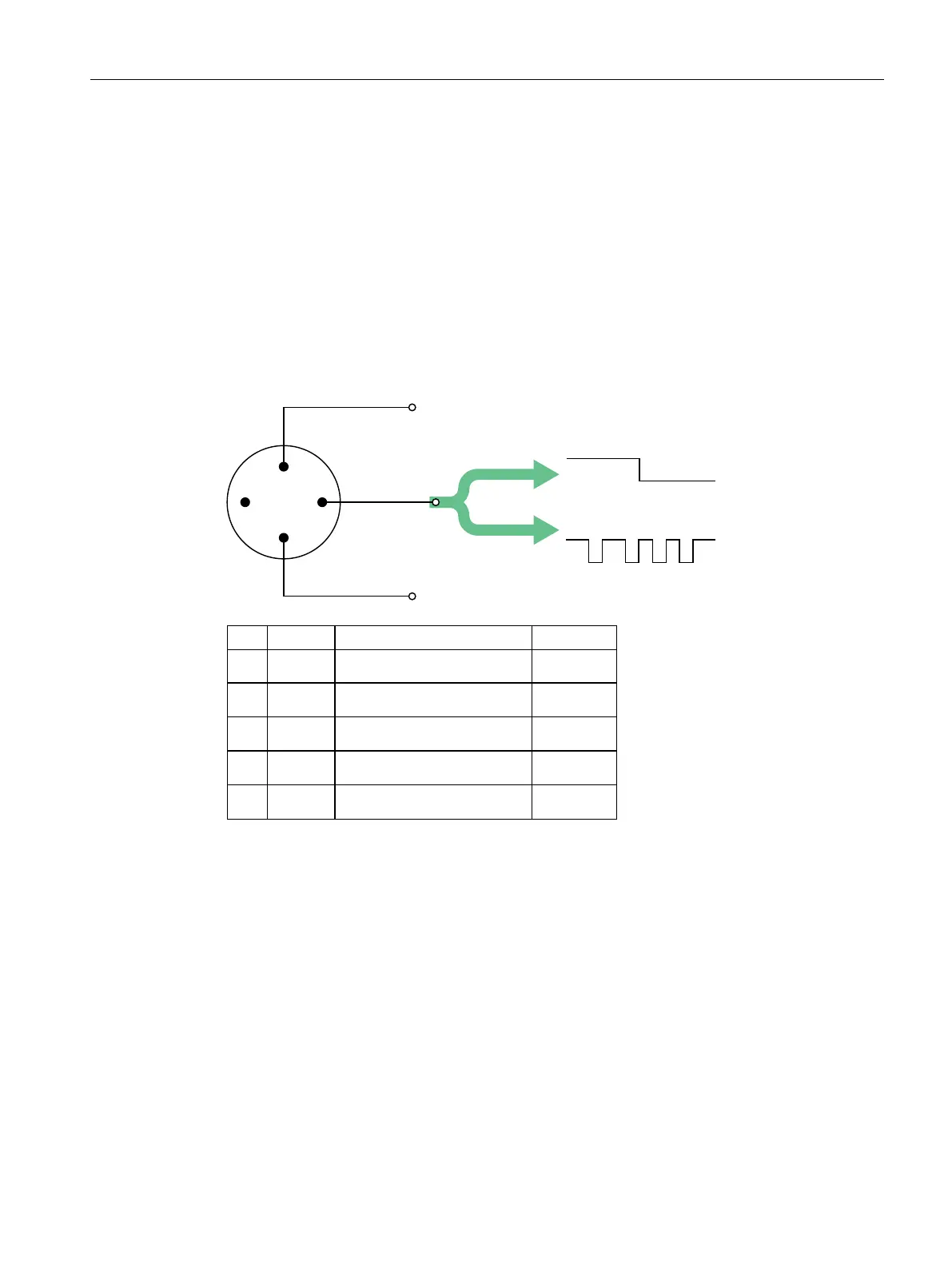
The pin assignment according to IEC 60974-5-2 is specified as follows:
•
Pin 1: 24 V
•
Pin 3: 0 V
•
Pin 4: Switching and communication cable (C/Q)
In addition to IO Link communication, these three pins also implement the power supply of
the device.
Detailed information about the power supply can be found in the documentation of the
utilized IO-Link master.
NESV
6WDQGDUG'HILQLWLRQ6LJQDO3LQ
QRWGHILQHG
6ZLWFKLQJVLJQDO','46,2
FRGHGVZLWFKLQJVLJQDO,2/LQN
6WDQGDUG,2
,(&
,(&
,(&
,(&
8
6
/
0/
4
&
8
6
/
0/
&4
6,2
,2/LQN
6,2
9
9
Figure 2-2Pin assignment IO-Link device
11
System overview
2.3 IO-Link interface
IO-Link system
Function Manual, 07/2022, A5E31637677-AC