IO-Link system
Function Manual, 07/2022, A5E31637677-AC
18
Integration into the automation system
3
3.1 Configuration of the IO-Link system
Introduction
An IO-Link system is configured in several steps. In the first step, the master is integrated in
the automation system and configured. In the second step, the IO-Link devices are
configured.
Integration in the automation system
When using a SIMATIC S7 CPU, use the engineering tool STEP7, V5.x or STEP7 (TIA Portal) for
configuration.
The IO-Link system is represented by the IO‑Link master in the configuration of the
automation system or the fieldbus and integrated with STEP7 or a GSD file.
The IO-Link master itself can be a field bus node (e.g. ET200ecoPN IO‑Link master) or a part
of the modular IO system that is connected to the field bus (e.g. ET200SP IO-Link master). In
both cases, the number of ports, the address range and the module properties are described
in STEP7 or in the GSD file.
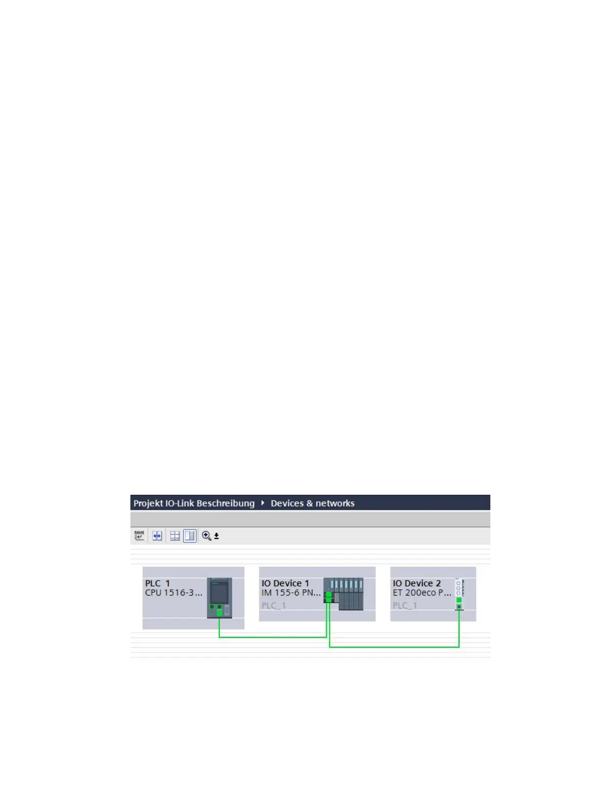
Example configuration in STEP7 (TIA Portal)
The figure below shows a PROFINET configuration with integrated PROFINET devices
ET200SP and ET200eco PN with IO-Link masters.
Figure 3-1Configuration of a PROFINET network with lower-level IO-Link masters