Haftungsausschluss
Wir haben den Inhalt der Druckschrift auf Übereinstimmung mit der beschriebenen Hard- und
Software geprüft. Dennoch können Abweichungen nicht ausgeschlossen werden, so dass wir für
die vollständige Übereinstimmung keine Gewähr übernehmen. Die Angaben in dieser Druckschrift
werden regelmäßig überprüft, notwendige Korrekturen sind in den nachfolgenden Auflagen
enthalten.
Abbildungen
Das vorliegende Dokument enthält Abbildungen zu den beschriebenen Geräten und Zubehör.
Die Abbildungen können bezogen auf das gelieferte Gerät und Zubehör in Einzelheiten abweichen.
Illustrations
This document contains illustrations of the described devices and accessories.
The illustrations may deviate from the particularities of the delivered device and accessories.
Technische Support-Zentrale
Central Technical Support
https://support.industry.siemens.com
Reparatur und Ersatzteile
Service and spare parts
https://support.industry.siemens.com/sc/de/en/sc
© Siemens AG 2019. All rights reserved
A5E40503606-AD, 11/2019
Disclaimer of Liability
We have reviewed the contents of this publication to ensure consistency with the hardware and
software described. Since variance cannot be precluded entirely, we cannot guarantee full
consistency. However, the information in this publication is reviewed regularly and any necessary
corrections are included in subsequent editions.
Siemens AG
Digital Industries
Postfach 48 48
90026 NÜRNBERG
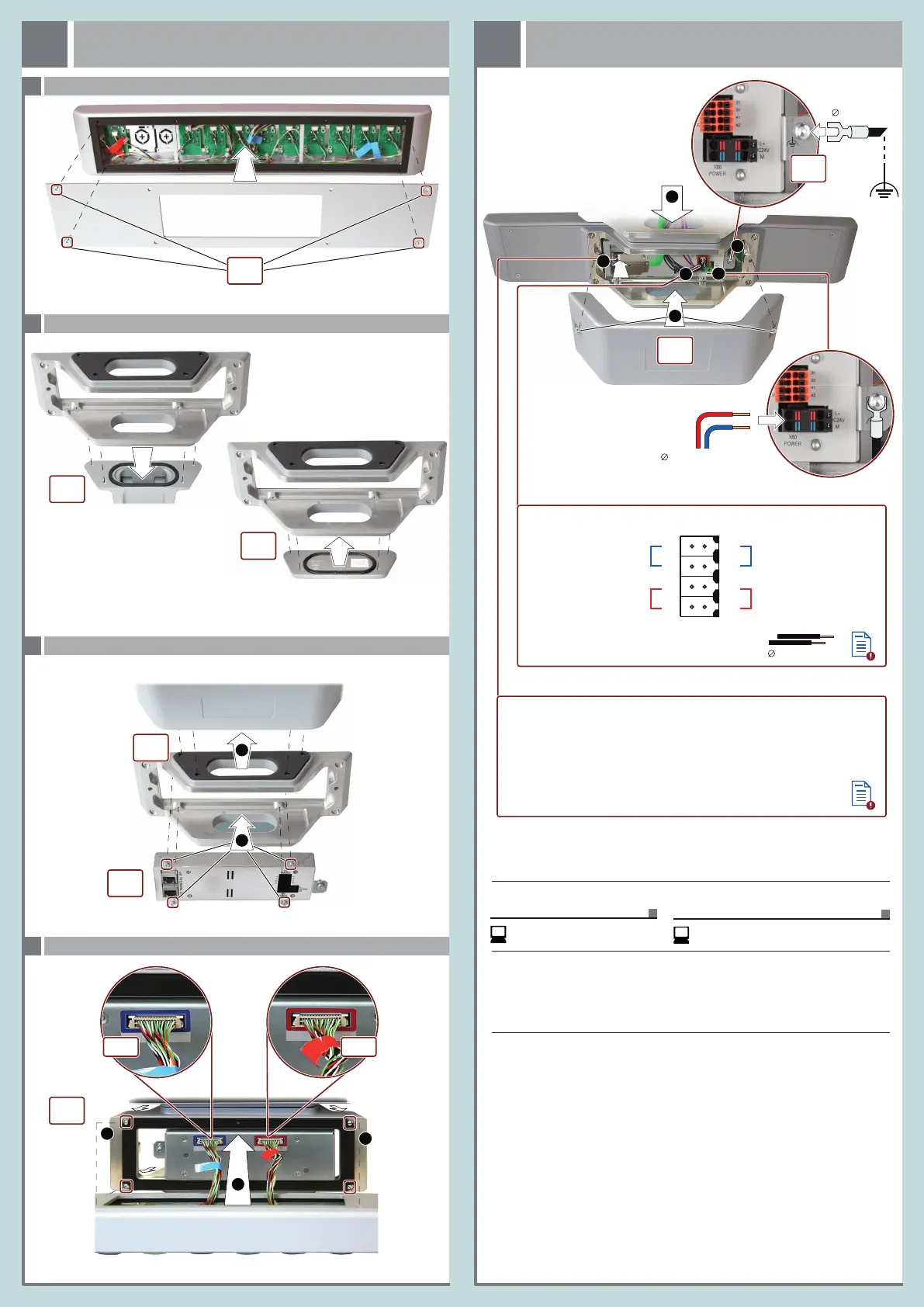
3.1
Front zusammenbauen – Mounting the front
1
2
2
X17
Vorderseite / Front side
Rückseite / Rear side
Rückseite / Rear side
X15
Rückseite / Rear side
1
Unterer Deckel aus dem Lieferumfang des PRO-Geräts
Lower cover from the scope of delivery of the PRO device
SIMATIC PRO-Gerät / SIMATIC PRO device
1
4 x T10,
0.8 Nm
4 x T20,
2.5 Nm
3.3
Front anbauen und anschließen – Mounting and connecting the front
4 x T20,
1.5 Nm
3.2
Standfuß- oder Tragarmmontage – Pedestal or support arm mounting
Standfußmontage / pedestal mounting
Tragarmmontage / support arm mounting
4 x T20,
2.5 Nm
4 x T20,
1.5 Nm
2
3.2
PRO-Gerät und Kommunikationsmodul – PRO device and communication module
6
2 x T20,
1.5 Nm
Rückseite / Rear side
4 x T20,
1.5 Nm
Extension Unit anbauen
Mounting the Extension Unit
3
Extension Unit anschließen
Connecting the Extension Unit
4
35
4
0.14 ... 1.5 mm
2
Leitungen/cables X10:
0.25 ... 2.5 mm
2
+
–
Bedienelemente projektieren / Configuring operator controls
Verdrahten Sie die Standard-Bedienelemente über die Projektierung im TIA Portal.
Die Schaltstellungen der Standard-Bedienelemente und die Beschreibung der
zugehörigen Eingangsbits finden Sie in der Betriebsanleitung.
2.5 ... 4 mm
2
T20,
1.5 Nm
2
11
12
31
32
21
22
41
42
X10
EMERG.
Safety-Bedienelement links
Safety operator control left
Safety-Bedienelement links
Safety operator control left
Safety-Bedienelement rechts
Safety operator control right
Safety-Bedienelement rechts
Safety operator control right
Wire the Standard operator controls via configuration in the TIA Portal.
You will find the Standard operator controls‘ switching settings and the
description of the corresponding input bits in the operating instructions.
C
M
Y
CM
MY
CY
CMY
K
hmi_extension_unit_pn_quick_install_guide_page_2.eps 1 12.11.2019 10:13:15hmi_extension_unit_pn_quick_install_guide_page_2.eps 1 12.11.2019 10:13:15