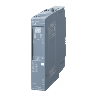
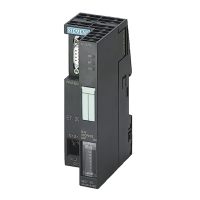
Do you have a question about the Siemens SIMATIC 6ES7134-4FB01-0AB0 and is the answer not in the manual?
Explains the manual's scope and purpose in supplementing operating instructions.
Outlines the general knowledge needed for understanding the manual.
Defines which ET 200S module this manual applies to.
Provides information on environmentally compliant recycling and disposal of the module.
Offers contact points for further questions and resources.
Information on Siemens training courses for the ET 200S and SIMATIC S7 system.
Contact methods for technical assistance with A&D projects.
Details online resources like knowledge bases and newsletters.
Presents the key features and input ranges of the 2AI U ST analog module.
Details the terminal connections and assignments for the 2AI U ST module.
Lists the compatible terminal modules for the 2AI U ST analog input module.
Illustrates the functional block diagram of the 2AI U ST analog input module.
Provides comprehensive technical data including dimensions, weight, and electrical specifications.
Lists and describes configurable parameters for the analog input module.
Configuration for module-level diagnostics (e.g., assignment errors).
Configuration for channel-specific diagnostics (e.g., wire break, overflow).
Parameter for setting digital filtering levels for measured values.
Parameter to define the input signal type and measuring range.
Detailed explanation of the smoothing parameter and its step response.
Explains the module's LED indicators for status and error reporting.
Details specific error codes, their meanings, and recommended remedies.
Explains how analog signals are acquired and converted to digital values.
Describes the binary representation of analog values in SIMATIC S7 format.
Details the decimal and hexadecimal values for ±5V and ±10V measuring ranges.
Details the decimal and hexadecimal values for the 1 to 5V measuring range.
Shows measured values during wire break events based on diagnostics settings.
Explains how PLC supply voltage and operating state impact analog input values.
Describes how input values falling within/outside ranges affect module response.
Guide on connecting sensors, including cable types and shielding.
Details the electrical isolation characteristics of the analog input modules.
Steps for connecting measuring encoders to analog inputs, considering isolation.
Defines abbreviations used in connection diagrams and text.
Explains how to connect isolated measuring encoders and the required wiring.
Details the connection procedure for non-isolated measuring encoders.
Provides rules and methods for wiring unused input channels on the module.
Recommends practices for connecting cable shields to prevent interference.
The Siemens SIMATIC ET 200S 2AI U ST analog electronic module (6ES7134-4FB01-0AB0) is a distributed I/O component designed for acquiring continuously variable analog signals, such as those from temperature or resistance measurements, and converting them into digital values for further processing within an automation system. This manual, dated April 2007, provides comprehensive information for commissioning and operating the module, supplementing the general ET 200S Distributed I/O System Operating Instructions.
The 2AI U ST analog electronic module features two inputs for measuring voltage. It supports several input ranges: ±10 V, ±5 V, and 1 V to 5 V, all with a resolution of 13 bits plus sign. The module is electrically isolated from the load voltage L+, and also between its channels and the backplane bus, as well as between the channels and the load voltage L+. However, there is no electrical isolation directly between the channels themselves. The permissible common mode voltage (UCM) between the inputs and MANA is 2 VACSS, and between MANA and the central grounding point (UISO) is 75 VDC / 60 VAC. The module is designed for an extended temperature range from 0 to 50°C when installed vertically.
Analog values are represented in two's complement, with the sign (S) always in bit number 15. The module offers digital filtering for smoothing measured values, adjustable in four steps: None, Weak, Medium, and Strong. The smoothing factor (k) multiplied by the module's cycle time determines the time constant of the filter. A higher smoothing factor results in a greater time constant.
The module supports various diagnostic functions. A red "SF" LED indicates group errors, which can include parameter assignment errors, internal errors, or issues with the load voltage. Specific diagnostic messages are readable, covering conditions like overflow/underflow, wire breaks (for the 1 to 5 V measuring range), upper limit exceeded, lower limit value undershot, and open circuits.
The module is designed for ease of integration into the ET 200S distributed I/O system. It requires basic knowledge of automation engineering for setup and operation. Commissioning and operation should only be performed by qualified personnel.
| Brand | Siemens |
|---|---|
| Model | SIMATIC 6ES7134-4FB01-0AB0 |
| Category | I/O Systems |
| Language | English |


 Loading...