Analog value representation
4.4 Effect on analog value representation
2AI U ST analog electronic module (6ES7134-4FB01-0AB0)
18 Manual, 04/2007, A5E01076000-01
4.4 Effect on analog value representation
4.4.1 Effect of the supply voltage and the operating state on analog input values
The input values of the analog modules are dependent on the supply voltage for
electronics/encoders and on the operating state of the PLC (CPU of the DP master). This is
illustrated by the table below.
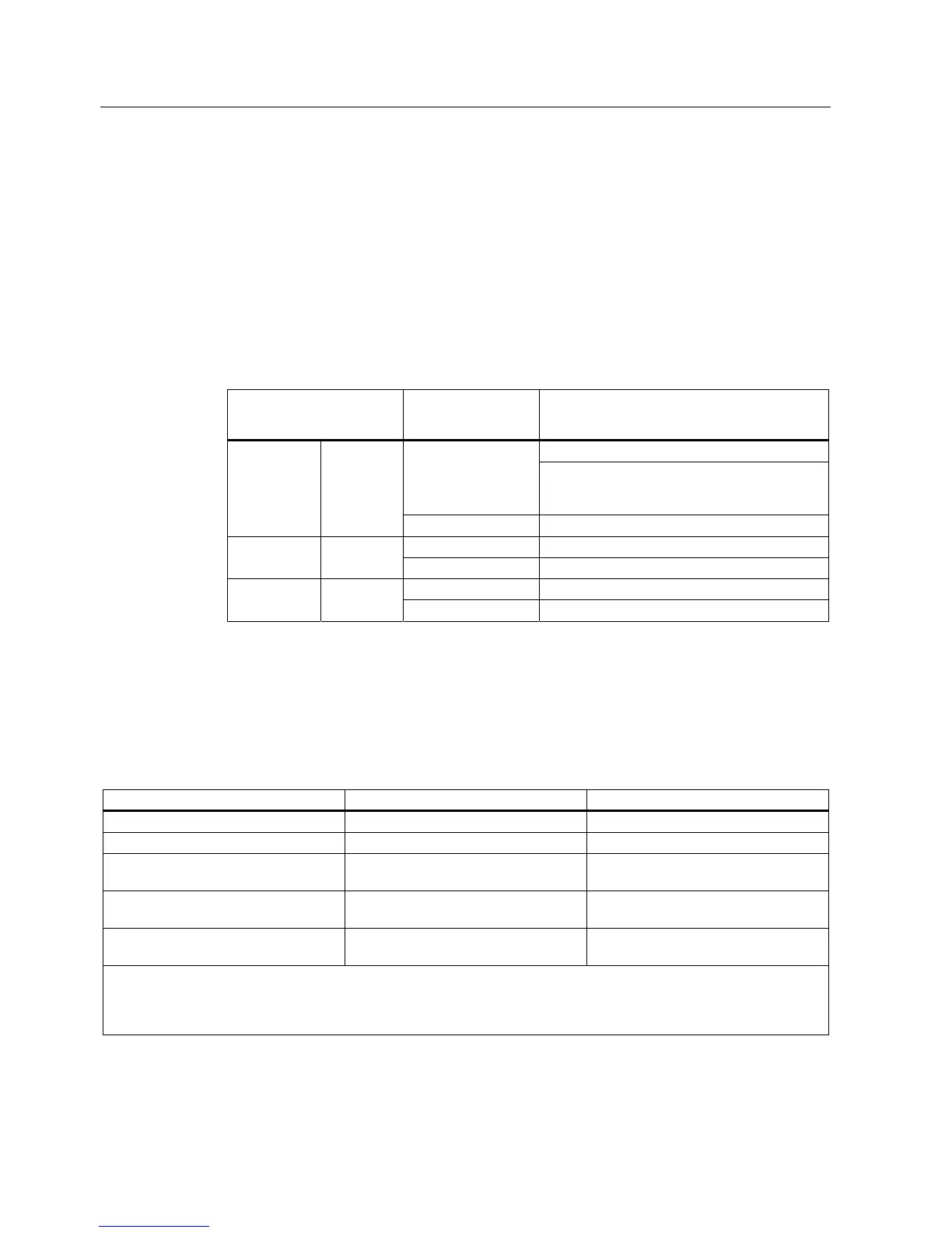
Table 4-6 Relationship between the analog input values for the operating state of the PLC (CPU of
the DP master) and the supply voltage L+
Operating state of the PLC
(CPU of the DP master)
Supply voltage L+ on
ET 200S (power
module)
Input value of the electronic module with analog
inputs (evaluation possible on the CPU of the
DP master)
Process values L+ present
7FFF
H
until first conversion after startup, or
after assignment of parameters for the module
is completed.
POWER ON RUN
L+ missing 7FFF
H
L+ present Process value POWER ON STOP
L+ missing 7FFF
H
L+ present - POWER OFF -
L+ missing -
4.4.2 Effect of the value range on the 2AI U ST analog input
The way electronic modules respond to analog inputs depends on where the input values fall
within the value range. This is illustrated by the table below.
Table 4-7 Response of the analog modules, depending on where the analog input value falls within the range of values
Measured value within ... Input value in SIMATIC S7 format Input value in SIMATIC S5 format
Nominal range Measured value Measured value
Over-/underrange Measured value Measured value
Overflow 7FFF
H
End of the overshoot range +1 plus
overflow bit
Underflow 8000
H
End of the underrange -1 plus overflow
bit
Prior to parameter assignment, or with
incorrect parameter assignment
*
7FFF
H
7FFF
H
*
With product version 1 of the 2 AI U ST, the following applies: If the parameter setting error diagnostic message is
triggered because the parameters have been assigned incorrectly (e.g., wire break in measuring range ± 20 mA), the SF
LED on the module lights up and the diagnostics can be evaluated. With this status, the correct input values are sent to the
DP master.

 Loading...