13
Analog Inputs and Outputs Analog inputs and outputs are continuous, variable signals.
Typical analog signals vary from 0 to 20 milliamps, 4 to
20 milliamps, or 0 to 10 volts.
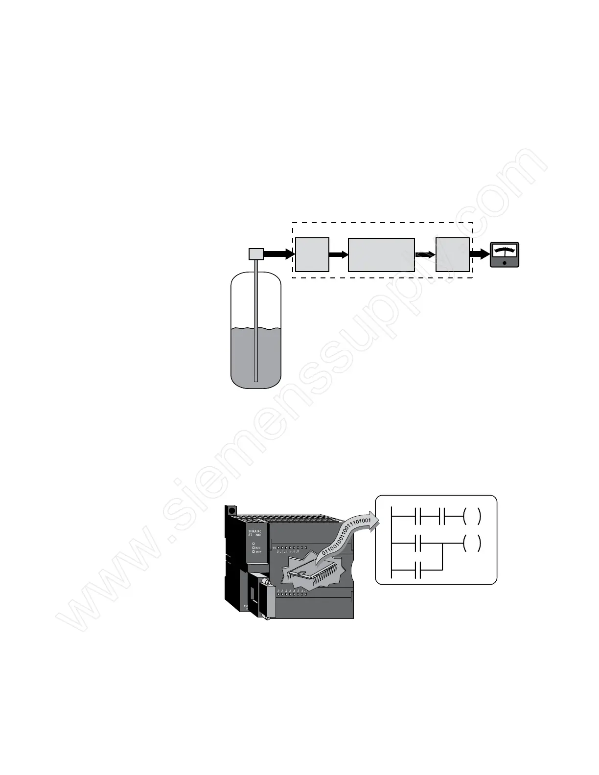
In the following example, a level transmitter monitors the level
of liquid in a storage tank and sends an analog signal to a PLC
input. An analog output from the PLC sends an analog signal to
a panel meter calibrated to show the level of liquid in the tank.
Two other analog outputs, not shown here, are connected to
current-to-pneumatic transducers that control air-operated flow-
control valves. This allows the PLC to automatically control the
flow of liquid into and out of the storage tank.
Central
Processing
Unit
(CPU)
Analog
Input
Analog
Output
PLC
0
0.2
0.4
0.6
0.8
1.0
Level
Transmitter
Storage
Tank
Panel
Meter
CPU The central processor unit (CPU) is a microprocessor system
that contains the system memory and is the PLC’s decision-
making unit. The CPU monitors inputs, outputs, and other
variables and makes decisions based on instructions held in its
program memory.
SF/DIAG
I0.0
I0.1
Q0.0
Q0.1
I0.4
I0.5
 Loading...


