14
Ladder Logic Programming A program consists of instructions that accomplish specific
tasks. The degree of complexity of a PLC program depends
upon the complexity of the application, the number and type of
input and output devices, and the types of instructions used.
Ladder logic (LAD) is one programming language used with
PLCs. Ladder logic incorporates programming functions that are
graphically displayed to resemble symbols used in hard-wired
control diagrams.
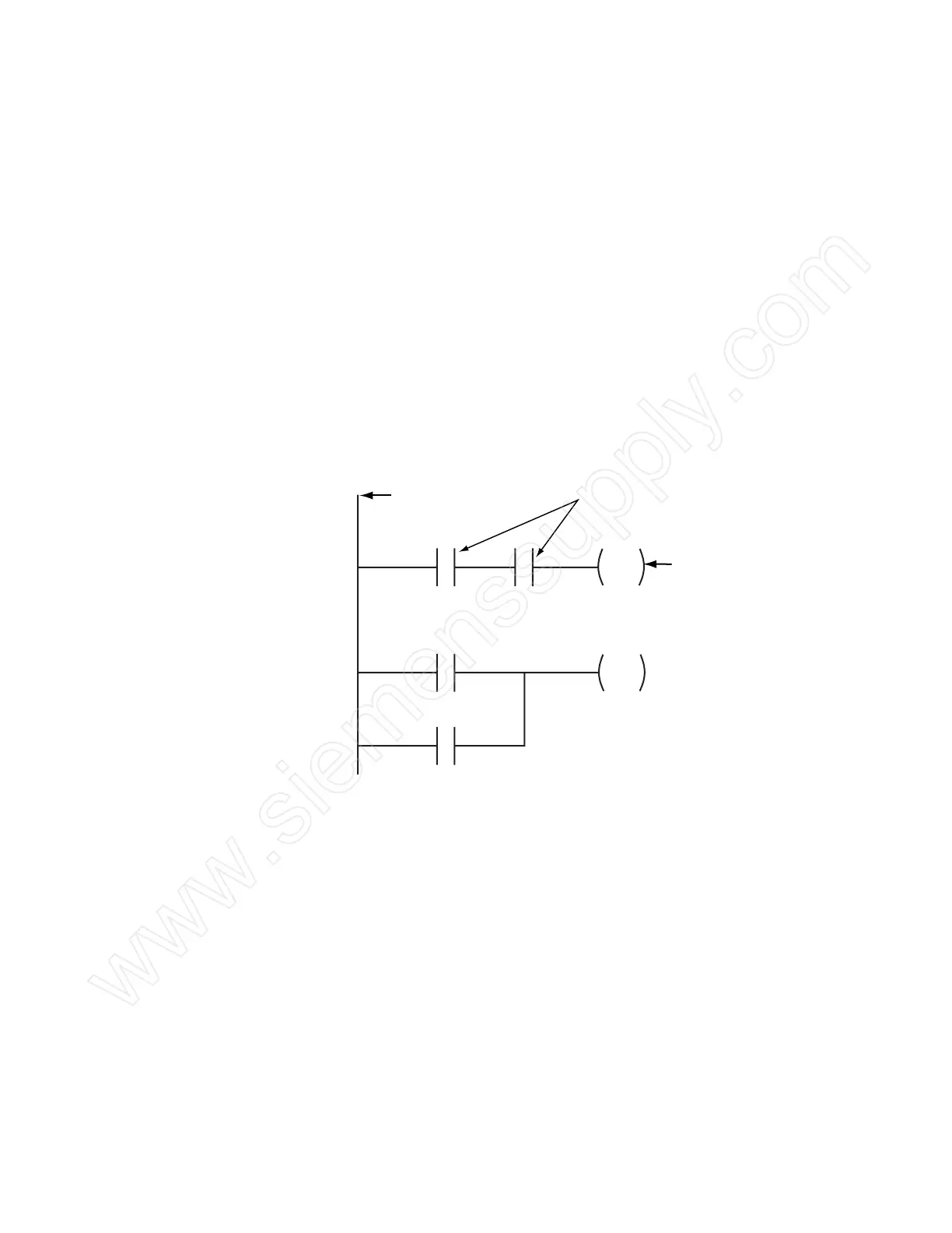
The left vertical line of a ladder logic diagram represents the
power or energized conductor. The output coil instruction
represents the neutral or return path of the circuit. The right
vertical line, which represents the return path on a hard-wired
control line diagram, is omitted. Ladder logic diagrams are read
from left-to-right and top-to-bottom. Rungs are sometimes
referred to as networks. A network may have several control
elements, but only one output coil.
Power Conductor
Network 1
Network 2
I0.0 I0.1 Q0.0
Output Coil Instruction
Normally Open Contact Instructions
I0.4
I0.5
Q0.0
Statement List and While ladder logic programs are still common, there are many
Function Block Diagrams other ways to program PLCs. Two other common examples are
statement list and function block diagrams.
Statement list (STL) instructions include an operation and an
operand. The operation to be performed is shown on the left.
The operand, the item to be operated on, is shown on the right.
Function block diagrams (FBD) include rectangular functions
with inputs shown on the left side of the rectangle and outputs
shown on the right side.
 Loading...


