38
Testing a Program Once a program has been written, it needs to be tested and
debugged. One way this can be done is to simulate the field
inputs with an input simulator, such as the one made for the
S7-200 PLC.
The program is first downloaded from the programming device
to the CPU. The selector switch is placed in the RUN position.
The simulator switches are operated and the resulting indication
is observed on the output status indicator lamps.
Contact and Coil Status After a program has been loaded and is running in the PLC, the
actual status of ladder elements can be monitored using STEP 7
Micro/WIN software.
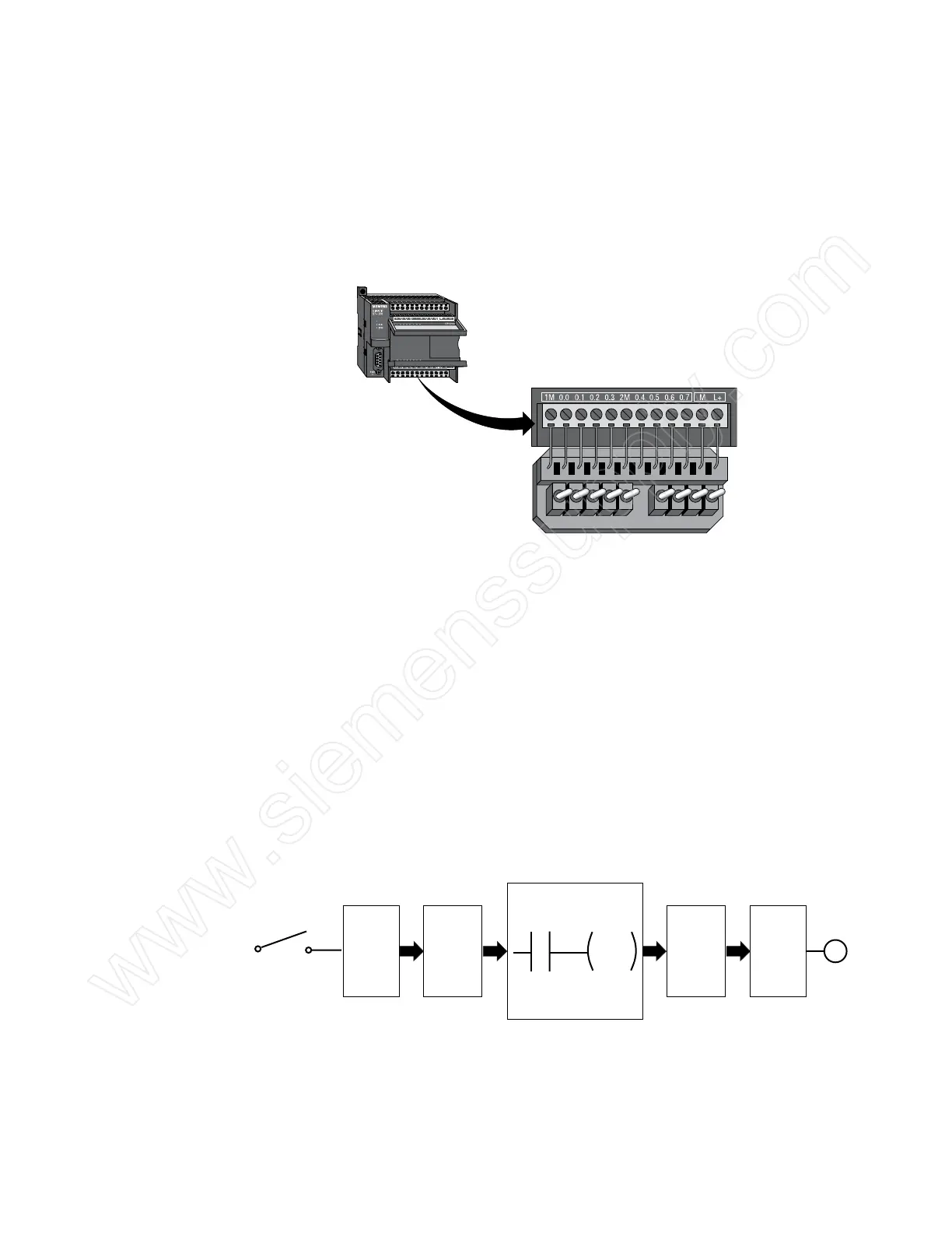
For example, in the following illustration, the toggle switch
controls the status bit for I2.1. As long as the toggle switch is
open, the I2.1 status bit is a logic 0. The I2.1 status bit controls
the I2.1 normally open contact. Because the I2.1 status bit is
a logic 0, the normally open contact function is open and no
power is passed to the Q3.1 coil function. As a result, the Q3.1
status bit remains a logic 0 and output point Q3.1 is off.
Toggle Switch
Input
Point
I2.1
OFF
Output
Point
Q3.1
OFF
Lamp
CPU Program
I2.1 Q3.1
Input
Status Bit
I2.1
Logic 0
Output
Status Bit
Q3.1
Logic 0
 Loading...


