39
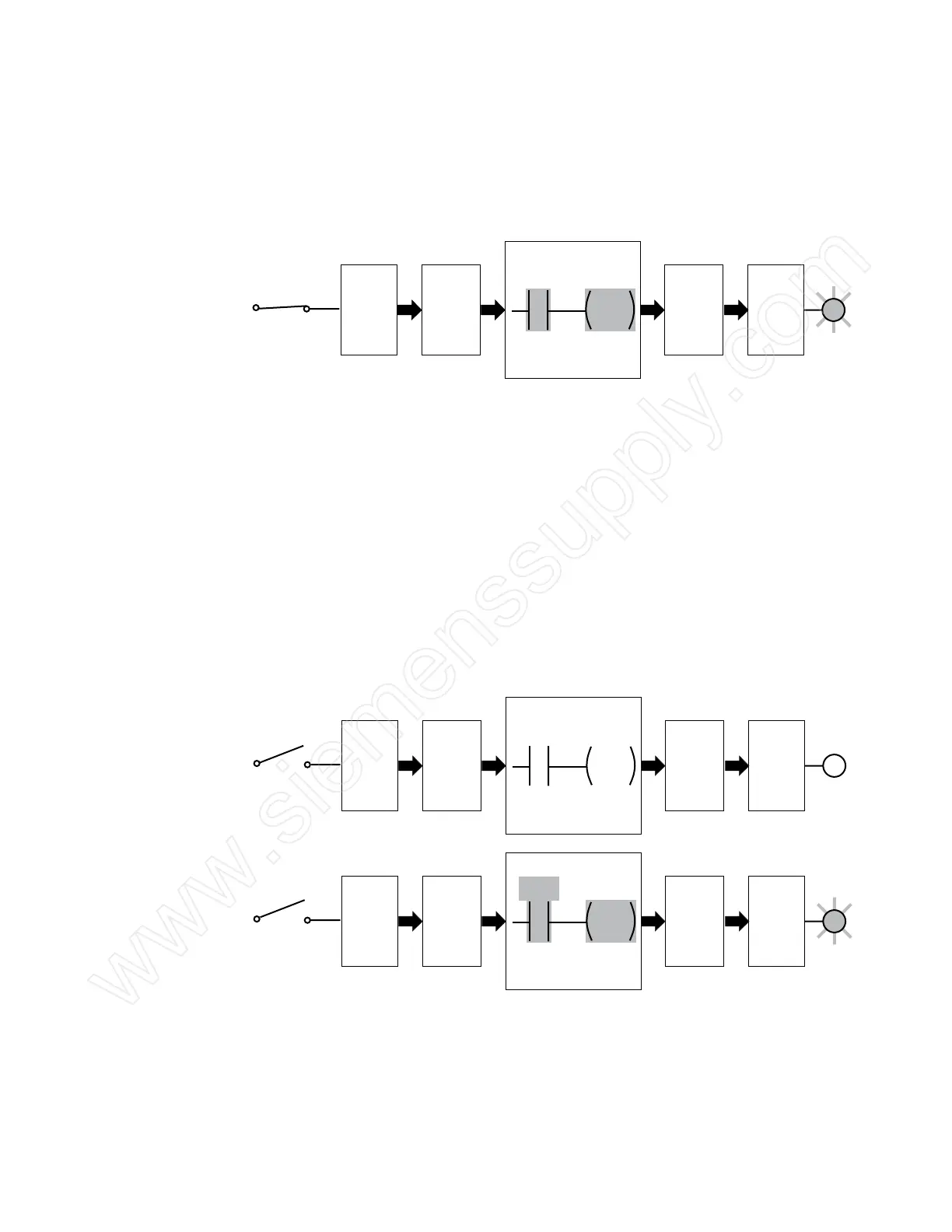
When the toggle switch closes, input point I2.1 turns on and
I2.1 status bit changes to a logic 1. This causes normally open
contact I2.1 to close and turn on Q3.1 coil. Note that a closed
contact and a coil that is on are shown highlighted in the
program. When Q3.1 coil turns on, the Q3.1 status bit goes to a
logic 1 and output point Q3.1 turns on. This causes the lamp to
light.
Toggle Switch
Input
Point
I2.1
ON
Output
Point
Q3.1
ON
Lamp
CPU Program
I2.1 Q3.1
Input
Status Bit
I2.1
Logic 1
Output
Status Bit
Q3.1
Logic 1
Forcing Forcing is another useful tool in the startup and maintenance
of a PLC system. Forcing overrides one or more input or output
status bits, causing them to stay in either a logic 0 or logic 1
status.
For example, in the following illustration, the toggle switch is
open. Under normal circumstances, the toggle switch would
have to be closed to turn on the lamp. However, if the I2.1
status bit is forced to a logic 1, the lamp will turn on, as long as
the program is functioning correctly and there are no hardware
or wiring problems. Similarly, the Q3.1 status bit could be forced
to a logic 1 to turn on the lamp.
Toggle Switch
Input
Point
I2.1
OFF
Output
Point
Q3.1
OFF
Lamp
CPU Program
I2.1 Q3.1
Input
Status Bit
I2.1
Logic 0
Output
Status Bit
Q3.1
Logic 0
Toggle Switch
Input
Point
I2.1
OFF
Output
Point
Q3.1
ON
Lamp
CPU Program
Input
Status Bit
I2.1
Logic 1
Output
Status Bit
Q3.1
Logic 1
I2.1 Q3.1
Forcing is useful not only to test and debug programs and
hardware during startup, but also to troubleshoot systems with
problems.
 Loading...


