Configuring the Central Rack
6-2
STEP 7 Getting Started
A5E00171228-01
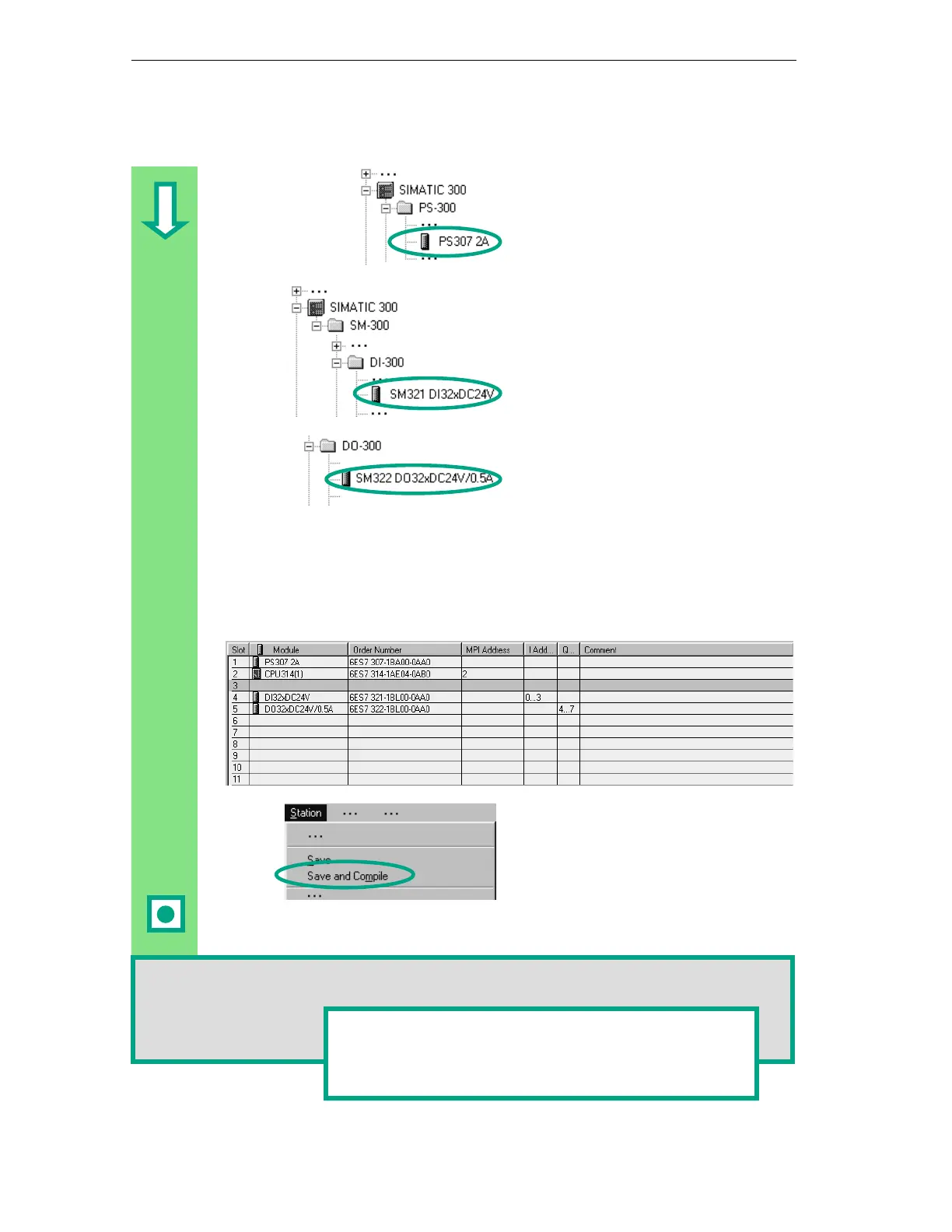
First you require a power supply
module. Navigate in the catalog until
you reach the PS307 2A and drag and
drop this onto slot 1.
Navigate until you find the input
module (DI, Digital Input) SM321
DI32xDC24V and insert this in slot 4.
Slot 3 remains empty.
In the same way, insert the output
module SM322 DO32xDC24V/0.5A in
slot 5.
In order to change the parameters (for example, address) of a module within a
project, double-click the module. However, you should only change the
parameters if you are sure you know what effects the changes will have on your
programmable controller.
No changes are necessary for the "Getting Started" project.
The data are prepared for transfer to
the CPU using the menu command
Save and Compile.
Once you close the "HW Config"
application, the System Data symbol
will appear in the Blocks folder.
You can also check your configuration for errors using the menu command Station >
Consistency Check. STEP 7 will provide you with possible solutions to any errors which
may have occurred.
You can find more information under
in
the topics "Configuring theHardware" and "Configuring
Central Racks."