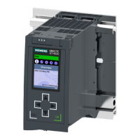
Do you have a question about the Siemens Simatic 6ES7 157-0AD81-0 A0 Series and is the answer not in the manual?
| Brand | Siemens |
|---|---|
| Model | Simatic 6ES7 157-0AD81-0 A0 Series |
| Category | Industrial Equipment |
| Language | English |
Indicates potential for death or severe injury if precautions are not taken.
Indicates potential for death or severe injury if precautions are not taken.
Specifies that only authorized personnel should install and operate equipment.
Provides guidelines for the proper application and handling of the device.
Explains the manual's objective: configuring, installing, wiring, and commissioning couplers.
Lists necessary prerequisites for understanding the manual's content.
Details modifications and new features in the current manual version.
Specifies the requirement for STEP 7 software for device configuration.
Introduces DP/PA coupler and DP/PA link as key bus coupling components.
Explains how bus couplings fit into the Siemens automation system architecture.
Describes the DP/PA coupler as a gateway between PROFIBUS-DP and PROFIBUS-PA.
Details the DP/PA link configuration with IM 157 and DP/PA couplers.
Explains the Y link's function as a gateway for redundant DP master systems.
Details the DP/PA coupler's applications, features, and special Ex [i] version.
Describes the IM 157 interface module's applications and features.
Explains the DP/PA link's operating principles and configuration options.
Details compatibility information for IM 157, Y coupler, and bus modules.
Covers general installation guidelines including orientation and mounting system.
Provides steps for installing the DP/PA coupler as a standalone device.
Details the procedure for installing the DP/PA link in non-redundant configurations.
Explains the installation process for the DP/PA link in redundant systems.
Provides steps for installing the Y link, requiring bus modules.
Discusses electrical isolation features and grounding requirements for system safety.
Details the specific wiring requirements for DP/PA coupler and links.
Explains how to connect the 24V DC power supply to the modules.
Describes the procedure for connecting the PROFIBUS-DP interface.
Provides important information and procedures for connecting PROFIBUS-PA.
Outlines the prerequisites and steps for commissioning the DP/PA link.
Details configuration for S7 standard and redundant operation modes.
Explains configuration using device master files for DP standard master.
Describes how to set the PROFIBUS address for the IM 157 module.
Outlines prerequisites and steps for commissioning the Y link.
Details the configuration process for the Y link in STEP 7.
Explains how to configure the DP slaves connected to the Y link.
Describes the start-up delay phase and its behavior.
Details the start-up behavior of the IM 157 in different operational modes.
Explains how the IM 157 behaves during specific events in redundant systems.
Covers methods for accessing module and slave records via SFCs.
Provides step-by-step instructions for replacing faulty IM 157, DP/PA, or Y couplers.
Details the procedure and prerequisites for updating the IM 157 firmware.
Explains the meaning of LED displays on the IM 157 for status and error indication.
Describes the LED indicators on the DP/PA coupler for status and errors.
Details the LED indicators on the Y coupler for status and error messages.
Explains the structure of slave diagnosis based on operation modes.
Details the structure and organization of diagnostic data blocks.
Describes how to read diagnostic data from underlying slaves using SFC 59.
Provides a practical example of evaluating diagnostic data in redundant operation.
Explains the principles of intrinsic safety for explosion protection.
Describes how field devices are supplied with power via the PROFIBUS-PA data line.
Details how to extend PROFIBUS-PA systems using DP/PA link couplers.
Explains the supported topology options for PROFIBUS-PA networks.
Covers general standards, approvals, and test criteria for the components.
Details the EMC behavior and interference immunity of the components.
Provides safety and installation information for hazardous Zone 2 areas.
Lists detailed technical data for the IM 157 interface module.
Provides detailed technical data for the Ex [i] version of the DP/PA coupler.
Lists detailed technical data for the standard DP/PA coupler.
Provides detailed technical specifications for the Y coupler.
Lists examples of DP slaves that can be configured directly in a Y link.
Shows a selection of field devices usable as DP slaves with various I/O ranges.
Lists order numbers for essential coupler components like IM 157 and DP/PA couplers.
Provides order numbers for PROFIBUS-DP bus connectors, cables, and terminators.
Lists order numbers for PROFIBUS-PA bus cables and SpliTConnect system components.
Defines an address as a unique network identifier for a node.
Defines a bus as a shared transmission path connecting multiple nodes.
Defines a coupler connecting PROFIBUS-PA and PROFIBUS-DP segments.
Explains device master files (GSD files) storing slave-specific characteristics.
Defines a DP master according to the IEC 61784-1 standard.
Defines a DP slave operating on the PROFIBUS bus system.
Defines PROFIBUS as a standard for process and field bus systems.
Defines PROFIBUS-PA for process automation, extending PROFIBUS-DP.


 Loading...