Installation
3-4
DP/PA Link and Y Link Bus Couplings
A5E00193841-011
3.3 Installing the DP/PA link for non-redundant operation
Required components
Rail for the S7 mounting system
IM 157
1 to 5 DP/PA couplers
One bus connector per DP/PA coupler (included)
Options for module exchange during operation:
– BM PS/IM or BM IM/IM bus module
– BM DP/PA coupler bus modules
You can find the order numbers for these components in Appendix D.
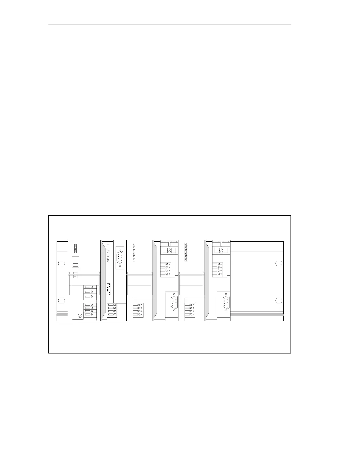
Typical configuration of the DP/PA link
The figure below shows the typical configuration of the DP/PA link with two DP/PA
couplers. The front doors are open.
PS 307 IM 157 DP/PA coupler
Bus connector
(not visible)
Rail
DP/PA coupler
Bus connector
(not visible)
Figure 3-1 Typical configuration of the DP/PA link for non-redundant operation

 Loading...


